Build It Yourself the Glen-L Way


We are starting at the point where the frames have been cut out and assembled. (For a description of how frames are assembled, see Frame Kits in the "About our Plans and Kits" directory.)
Building forms may vary in type but the principles are basically the same. The assembled frames are mounted on two longitudinal stringers that have been leveled both lengthwise and athwartship. Each of the frames is spaced the distance specified in the plans and centered. The frames are left loose until adjustments for minor descrepencies are made. Then the frames are attached to the form using wood blocking or metal angles. Usually the frames for inboards are fastened permanently as the set up members serve as motor stringers. The frames for other types of boats are most often only temporarily fastened. Refer to the plans for specific instructions. Of course, some small plywood boats use much simpler building forms, and in the case of Stitch-N-Glue boats, none at all.

The breasthook is a triangluar shaped piece of plywood that is attached to the stem to provide a place for the sheers to attach. The breasthook is glued and fastened to the stem before the stem is attached to the frame.
Here a plumb-bob is being used align the stem. The plans have given a distance from the set-up level to the top of the breasthook. Sufficient blocking is added to raise the breasthook to the proper position and the stem and breasthook assembly are firmly anchored in position.
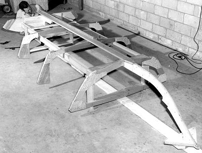
Since the keel in the after section of a planing hull, in profile is a straight line, it is best to align the transom by bringing it up to the proper height using a straight-edge on the keel to assure that this line is true. If a transom knee is called for, it can be used to determine the angle of the transom. After alignment the transom is anchored in position and braced to the form as necessary to assure it will not move during construction.
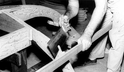
The chine is clamped in position while it is sprung around the frames to determine the correct angles for the frame notches. It is imperative that the chine mate firmly in the notches and does not merely bear on one corner of the frame.

The builder is shown using a scrap of plywood as a jig to determine the set-back of the chine from the forward edge of the stem. The stem will eventually be "faired" or beveled so the line formed by the chine will extend to the centerline of the stem. If the design utilizes a chine blocking member, as this one does, it may be necessary to adjust the chine blocking to compensate for the thickness of lumber you are using. Without chine blocking, the position (up or down) of the chine on the stem is determined by allowing the chine to take a smooth (fair) bend around the framework. Although the exact height can vary, the opposite chine should be at the same height.

Fitting the chine at the stem is accomplished as shown. Be sure to leave the chine long. Allow it to extend beyond the transom as subsequent fitting may require it to be moved forward.
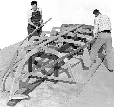
The stem should be braced to prevent movement when installing the chine. Chine (and sheer) lumber should be carefully selected for straight grain. Often the screw in the forward frame is left out when springing the chine into position. This eliminates the tendency of the chine to break at this point. The screw will be driven in when the planking is applied. The chine and all subsequent longitudinal members will be both fastened and glued in position.

The notches for the sheer (or sheer clamps) must be angled as was done for the chine. In some cases the sheer is built up from two laminations. It is imperative that the sheer members be set in vertically from midship forward. Attemping to twist and bend them to fit the planking contour will frequently cause them to break. Later in the fairing process the sheer will be beveled so that the planking will mate on a flat surface.

The sheer has been angled to butt properly to the stem and is now glued and fastened to the breasthook. Again, leave the sheer long until it is properly fitted to the stem.
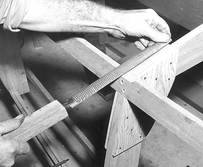
FAIRING: It will be necessary to "fair" the various longitudinals. One method is to file a notch conforming to the frame contour at each frame along the chine, sheer, and keel. The angle of intermediate notches can be determined by using a straight edge across members and gradually adjusting the notch until the straight edge rests on flat surfaces.

FAIRING: These longitudinal members are then planed to match the angle of the notches. Be sure that the resultant surface is "fair", without humps or dips.
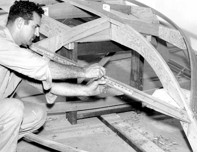
FAIRING: A line is drawn from the frame closest to the stem, or the next aft frame, to the center of the chine at the stem. The portion above this line must faired to provide a flat surface for the bottom planking to mate to. The side planking will be fastened to the portion below this line. In most instances, the chine will follow the angle of the side frames so that fairing the chine for the side planking is unnecessary.

FAIRING: Any minor discrepencies must be faired out of the frames. In planing boats, it is imperative that the longitudinal lines in the aft section be straight lines. Use a straight edge to determine fairness. Curved lines on a planing boat can cause "porpoising", or to ride bow down. Although this effect does not occur on displacement boats, lines should be fair for esthetic reasons and unfair lines will have some effect on performance.

FAIRING: To insure that the longitudinal lines are smooth, even, fair curves, stand back occasionally and sight along the area being faired. Dips and humps must be removed. If necessary another thin piece of wood can be glued into low spots and the area re-faired.
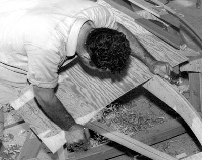
FAIRING: A short length of plywood is used to check the fairing in the forward portion of the boat. Considerable material may have to be removed along the stem to provide a solid landing for the bottom planking. Note that sheet planking will naturally bend to form a convex surface.

FAIRING: A short length of plywood is also used to check the fairing for the side planking.

PLANKING "PATTERN": Fitting the planking is easiest done by leaning the panel against the side of the boat and roughly marking to shape. Don't leave any more material overhanging than necessary as scraps may be utilized in other parts of the boat. Note: We are frequently asked, "Where are the planking patterns?" In frame construction, minor differences in frame spacing would make patterns useless. The boat itself is the pattern.

All mating surfaces are coated with glue. A paint roller works well for this purpose. Follow the glue manufacturer's instructions and fasten panels in place before the glue sets as a good bond is imperative.
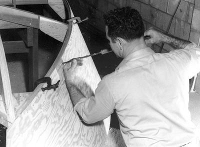
Usually several locating screws are used to position the panel while fitting and drilling for screws. The planking is fastened to the longitudinals, stem and transom only; not to the frames. After fitting and drilling, the panel is removed and all mating surfaces are coated with glue. The panel is then screwed in place. NOTE: The plywood panels shown in many of these photos are full length; it is more common to use standard 8' panels and join them with scarf joints or butt blocks.

After the first side panel is installed the excess along the stem is sawn off and planed smooth so that the second side will lap the first side. Here the builder is trimming the second side which will then be faired to match the first side.

BUTT BLOCK: Side and bottom planking usually require a junction to make the panels long enough. Although scarf joints can be used, the more common method is to use a butt block. Butt blocks are usually the same thickness of the planking being used. The joint is always made between the frames (not on the frames) in as flat an area as possible. Note that separate butt blocks are fitted between the battens. The planking is temporarily held in place, holes drilled into the butt blocks, the first planking section removed, and the butt blocks glued and fastened to the planking. The next planking section is installed after the first in glued and fastened in place, gluing and fastening to longitudinals and butt block.
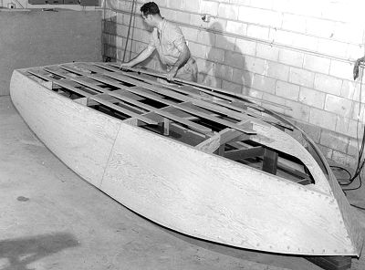
In designs that have frames notched for the battens, it is easiest to wait until after the application of the side planking before installing the battens. These members are notched into the frames the thickness of the lumber being used. After installing, check that the bottom lines are true. It may be necessary to fair or kerf the forward ends of the battens to conform to the shape of the bottom planking.
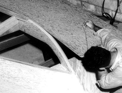
The bottom planking is clamped or located with several screws along the centerline of the keel. The forward end of the planking is roughly marked to shape and a line scribed along the chine. As much excess material as possible is cut away in the forward section to make it easier to force the planking into position.

TRANSITION JOINT: In the forward section there is usually a point where it is no longer practical to lap the bottom planking over the edge of the side planking. At a point we call the "transition joint", the bottom planking changes from lapping to butting to the side planking. At the stem, the side and bottom planking will be in-line. The photo below illustrates the appearance of the joint after the planking has been installed.
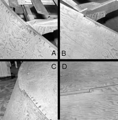
TRANSITION JOINT: These four photos illustrate the transition joint.
A Depicts the transition joint after the side planking has been applied. Note that forward of the cleft, the side planking is fitted to the line on the chine. Aft of this position, the planking is left projecting above the chine.
B Shows this same area after the projecting plywood planking has been faired, flush to the chine.
C Illustrates the appearance of the joint after the bottom planking has been applied. Observe that the portion forward of the bottom planking butts to the side planking. Aft of this area, an abrupt transition is made and the bottom planking laps the side planking.
D Shows the finished joint, as viewed from the side. The transition point is clearly illustrated, the area forward being butt joined, the portion aft, lap joined.

TRANSITION JOINT: One method of marking the line on the bottom panel, forward of the transition joint, is to coat the sharp edge of the side panel with chalk or crayon. The bottom panel is bumped on this edge to transfer the line to the underside of the bottom planking for subsequent cutting.
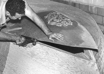
TRANSITION JOINT: It will be necessary to carefully hand-fit that portion of the bottom planking along the chine that will butt join to the side planking. NOTE: To facilitate bending, toweling has been placed on the area of most stress, boiling water poured on, and allowed to set several hours or over night.

In all cases, after fitting one panel, the contour should be marked to the panel for the other side. It is, of course, advisable to first check on the opposite side in case there are any variations.
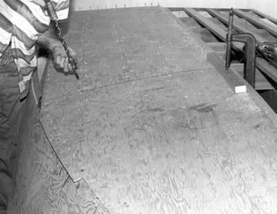
The bottom panel is liberally coated with glue and fastened into position. Note again the transition joint. The lapped portion, aft of this point, is left oversize and trimmed after the panel is fastened in place.

The two bottom panels will butt join along the keel until the curve of the stem becomes too severe. From this point forward the second half will lap the first panel. It is, therefore, necessary to fair the first panel as was done forward of the chine transition.
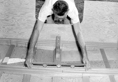
After righting the hull, it should be levelled and chocked securely in position. At this point of construction the hull could twist. It is imperative that the hull be held in position, and re-levelled if moved.
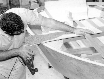
The planking extending above the sheer should now be removed. Depending on the type of boat, side decking, cabin, seats, etc. are installed

When intermediate deck beams are used, they should be blocked between the sheer clamps as shown. The battens are notched into the frames and deck beams and end against the sheer with a fitted bevel. If you do not wish to see the batten ends notched into the dash beam, the can be glued and fastened to blocking on the forward side of the dash beam. The strongback (center batten) can be partially notched into the breasthook and tapered to make a smooth flowing curve to the stem.
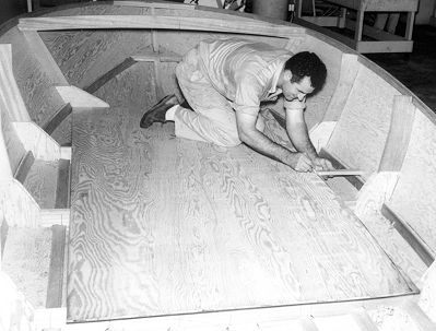
The floorboards are usually fitted soon after the hull has been righted to provide a flat work area for the builder. Here, the buider is using a stick to transfer the outline of the hull side to the floorboard panel. Floorboards are usually in several sections, with a removable center section for bilge inspection.
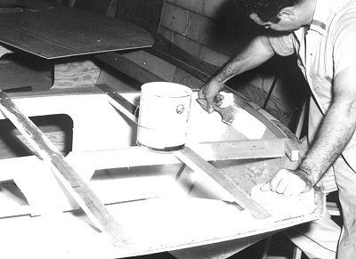
Be fore applying the decking, it is often advisable to paint or otherwise seal the forward area where later access will be difficult.
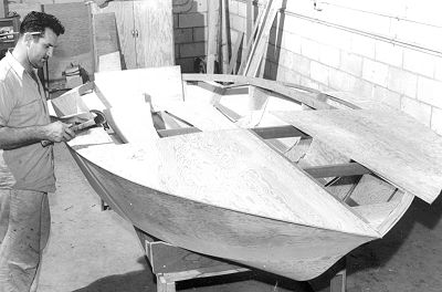
The sheet plywood decking is normally put on in two parts, with the junction over the strongback. The sheer edge is left oversize for fitting after the deck is glued and fastened in place.
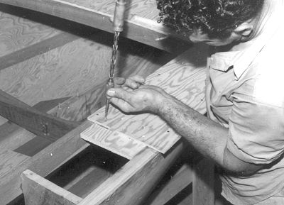
Butt joints are made along the side deck as required. Note that the foredeck extends along the side deck as long as the panel will allow. Joints near the deck beam will tend to crack after rough usage.

It is good practice to install much of the interior fittings, including through-deck chainplates (sailboats), steering and wiring, before the decking is installed. Many areas are not readily accessible after decking.
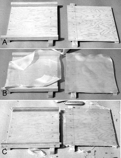
Centerboard and daggerboard trunks are fiberglassed on the inside before assembly. This protects the inside of the trunk from abrasion when the board is raised or lowered and also seals it against water damage. The photos above illustrate the normal procedure.
A Each half is assembled.
B Fiberglass cloth is fitted, then applied.
C The cloth is trimmed and any burrs sanded away.
The final step is to glue the two halves together. We would recommend using thickened epoxy and using a long dowel to form the resin that squeezes out on the inside into a small fillet. If a sailboat is going to leak, it will leak around the board. If the hull is fiberglassed on the outside, we would recommend tucking cloth, as far as practical, into the trunk to protect the exposed edge of plywood.
The hulls shown in the preceeding photos have all been planing powerboats. The procedures are much the same for plywood rowboats or sailboats, but because sailboats tend to have more "rocker" in the bottom, they may look different on the building form. Frames may not all mount directing on the building form. Some may have temporary braces across the frame that will rest on the building form. This will also apply to some powerboats. Other designs may use much abbreviated forms or in some cases, none at all. In all cases, the plans override any differences in the procedures shown.