DETERMINING CABLE LENGTH

For a single motor, add A, B, and C dimensions and deduct 20" from the total. For dual motors, measure as for single and add 1/2 of the motor spacing distance. Inboard and outdrive installations, measure along the actual cable routing from the centerline of the wheel to the hook-up point at the tiller or the steering lever. Deduct 18" from the total. If the resulting measurement is 3" or more over the even foot, order the next longest cable. Cables are available in 1' increments only.
NOTE: Steermaster replacement PARTS are no longer available, but REPLACEMENT CABLES are AVAILABLE
Steermaster was a very popular steering system among boat manufacturers in the '60s, '70s and '80s. As of 2005 it is no longer being manufactured and no parts are available from the manufacturer. The factory has no inventory and we know of no sources for replacement parts.
We have kept the pages giving technical information, but again, the ONLY PARTS AVAILABLE are Replacement Cables for these units.
"STEER MASTER" Replacement Cables
The Steermaster Single cable push-pull steering system was used by many boat manufacturers during the 1970's through the mid-1990's. These rugged units are no longer manufactured, but a few replacement cables are still available.
Determining Length for Replacement Cables
SteerMaster Mark II (with threaded end)


SteerMaster Mark III (flat end with hole)
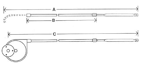

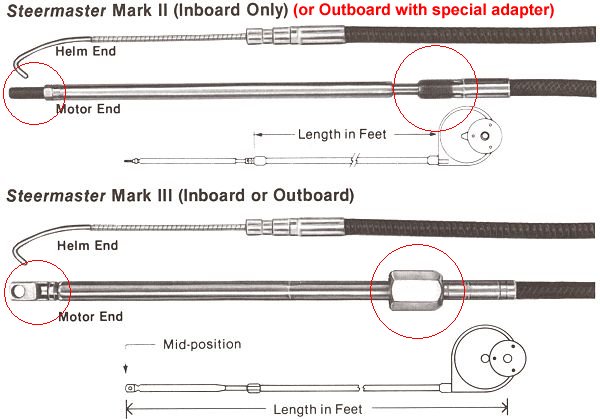
Notes:
The Mark II is an older configuration that has been "discontinued" for over 15 years. The system was designed for inboard installations, but hookup kits were made to adapt it to outboards. The difference between the Mark II and Mark III systems are all on the motor end. The red circles indicate the areas of difference. Complete Kits are no longer sold, although some replacement cables are available.
The Mark III Replacement Cables are available in limited quantities. The easiest identification is the cable end at the motor. The Mark II is threaded, the Mark III is flattened with a hole.
When replacing a cable, there may be any of various attachments or fittings not shown above. These are NOT part of the cable. Since some of these fittings may no longer be available, they should all be removed and saved when replacing an existing cable.
Both Mark II and Mark III use the same drum, which is marked "Mark II".
SteerMaster
Mark II and III
Installation Instructions
The following is from an old Steermaster installation sheet, with some changes to reflect changes in the hardware. The new owner of Steermaster will probably be updating the instructions to reflect current hardware, so read the instructions below carefully before installing and check to see if modifications need to be made to suit the hardware you have.
1. The SteerMaster kit is shipped completely assembled. It is normally shipped for starboard installation. The chart below shows the configurations for port and starboard outlet.
Chart 1 - Cable Outlet

2. If it is necessary to change location of the cable outlet, follow the instructions in Chart 2.
Chart 2 - Method of Changing Cable Outlet
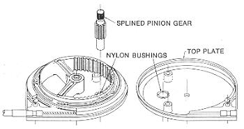
1. Remove the 4 bolts and lift off shaft housing and top cover.
2. Lift out pinon gear and reinstall so that the spline is opposite from what it was originally.
3. Reassemble, making certain that the nylon bushings are in the proper position.
Chart 3 - Mounting Steermaster to the Dash
3. Determine the position of bezel. Following the instructions in Chart 3, secure the bezel mounting bracket to the dash using the bolts provided.
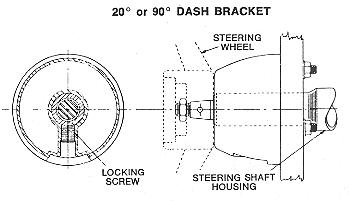
Determine where the Steermaster is to be mounted. Check for clearance behind dash or bulkhead before drilling any holes. When the position is determined, paste the drilling template that accompanies the Bezel Kit on the dash or bulkhead. Drill in accordance with the directions on the template. (Note: The drawing above shows the old style bezel. The current bezel consists of 2 parts: the black plastic bezel and a die-cast metal base. The holes template that accompanied the one I checked did not exactly match the bolt holes on the casting. Check the casting to the template before drilling. The photo below is of the bezel being supplied as of Sep 2002.)
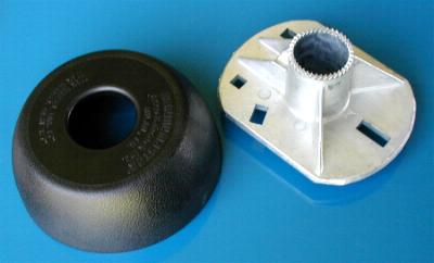
Fasten bezel mounting bracket securely in place using the bolts provided. Loosely thread in the Allen head locking screws into the bezel mounting bracket, slip the steering shaft through the bracket from the forward side of the dash or bulkhead, tighten the Allen head locking screw firmly by hand using the proper size Allen wrench.
4. Attach Steermaster cable at the motor end following instructions received with the Hook-Up Kit. (Note: There may no longer be a Hook-Up Kit for the older Steermaster II units, depending on type of installation. Check the Steermaster page for kits currently available.)
5. Winter Storage: For extended periods of storage, lubricate telescopic tube of push-pull generously. Turn cable to extended position, Coat with Marine Lubriplate, and retract the tube.
Difference between Steermaster Mark II and Mark III
STEERMASTER Parts Diagram
Note: The following is provided for your information only. Parts are no longer available for Steermaster systems, only replacement cables.
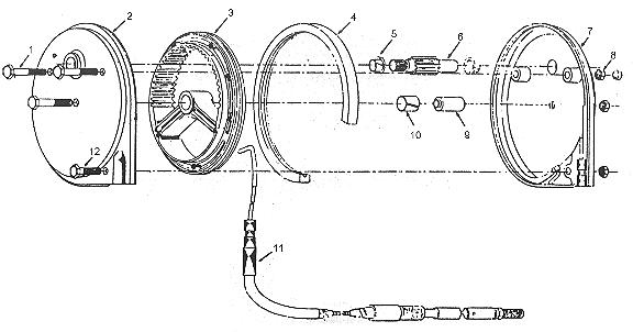
| Item | No. Req'd | Part No. | Descrition |
|---|
| 1 |
3 |
*RC-46-1-C |
Bolt-Hex |
| 2 |
1 |
*RC-440-2 |
Housing-Right |
| 3 |
1 |
ACC-53-2557-0019 |
Ring Gear |
| 4 |
1 |
*RC-441 |
Nylon Liner |
| 5 |
2 |
*RC-2-1 |
Bearing Nyliner |
| 6 |
1 |
*RC-443-CC |
Pinion |
| 7 |
1 |
*RC-440-1 |
Housing-Left |
| 8 |
4 |
*RC-59-2-C |
Nut-Conelock |
| 9 |
1 |
*RC-446 |
Bushing-Spacer |
| 10 |
1 |
*RC-512 |
Bearing-Nyliner |
| 11 |
1 |
*40795-11 |
Bushing-Spacer |
| 12 |
1 |
*RC-46-2-C |
Bolt-Hex |
|


