First attempt at making a steel boat, the Goliath-Pt 4
Posted by Dan Hennis on Jan 21st 2019
You can read Part One of this blog here
Part Two is here
Part Three is here
15 December, 2018-
Wow, time seems to fly these days.
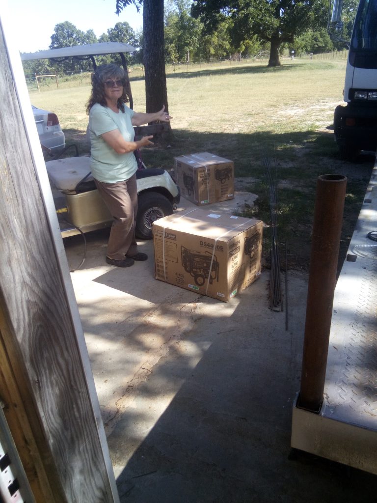
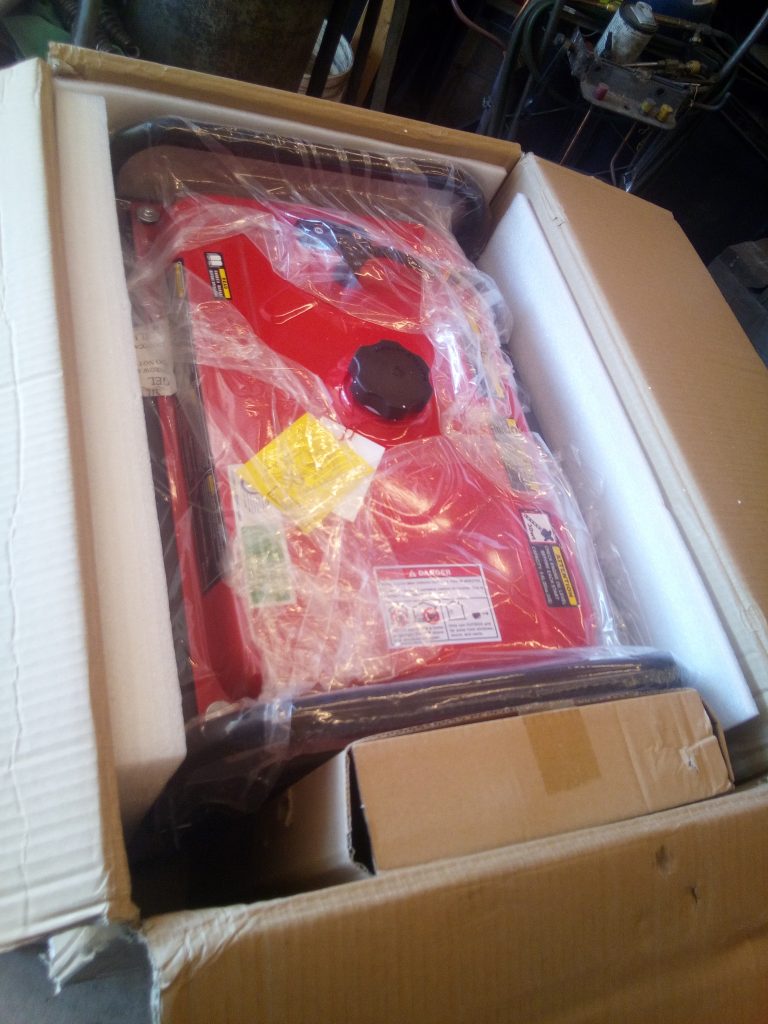
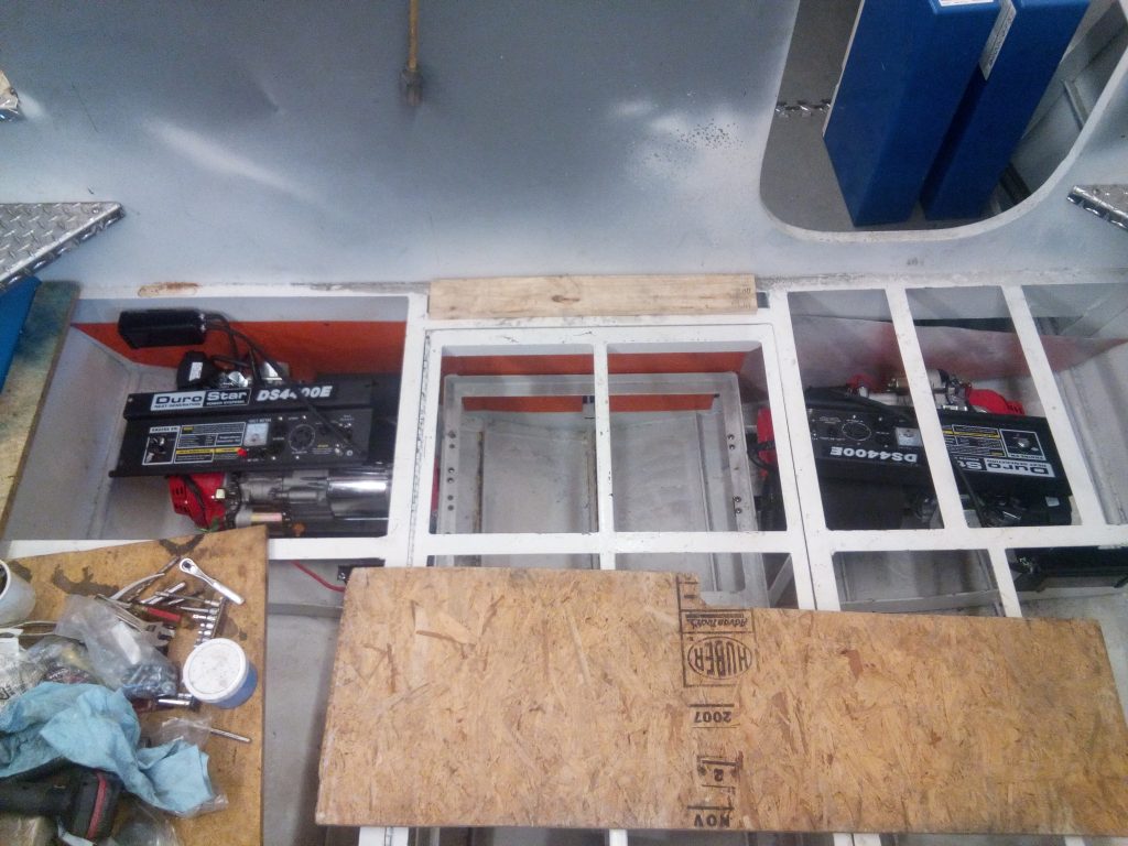
Since my last update, I got the pair of gensets, removed them from their frames, and started figuring out how I was going to get them in below the decks. There are several things that needed to be decided when I started. Where do the exhausts go, how do they get fuel, where are the dedicated starter batteries attached to or if I am even going to use them, how do I do the controls, (starters, chokes, etc, and in dual form...)
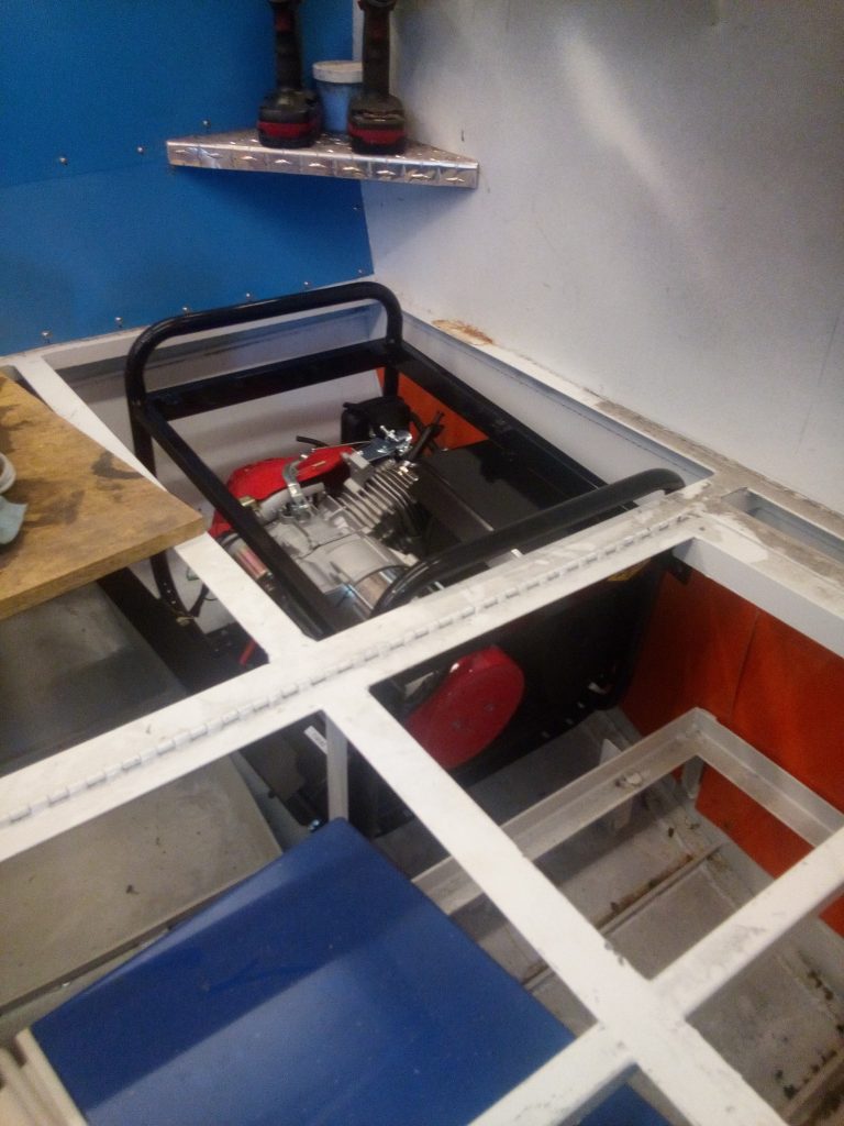
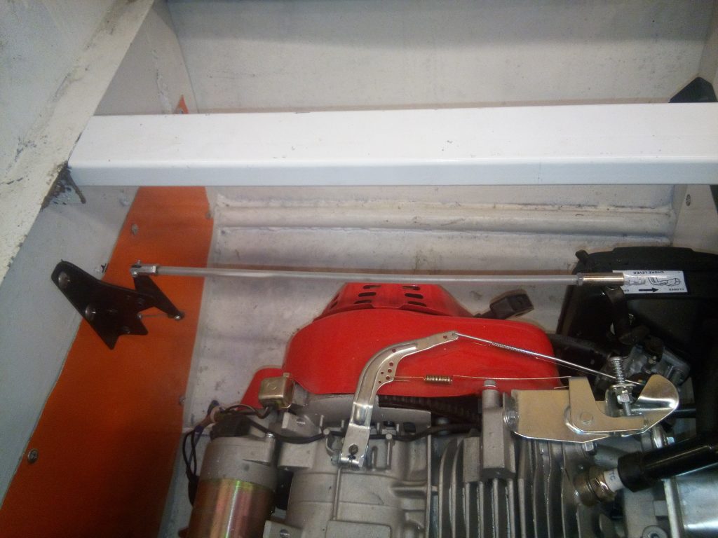
The installations used the original isolation mounts and just sat them in 2 rails bolted to the frames and stringers of the hull. The chokes required that I order the longest choke cable I could find, 120", and then make linkages to make them couple up correctly. The controls required a bit of engineering scavenged from the RC world, but works great. The linkages are different from port to starboard, due to orientation placement. I wanted both exhausts to exit via the pylon, so the gensets are placed accordingly.

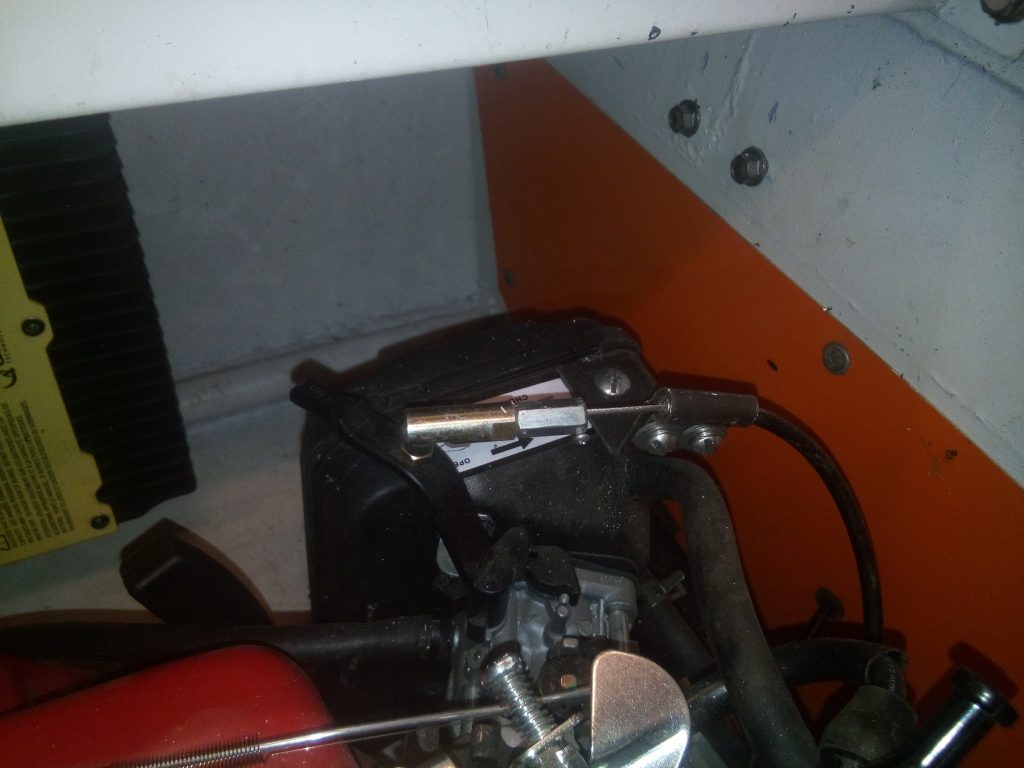
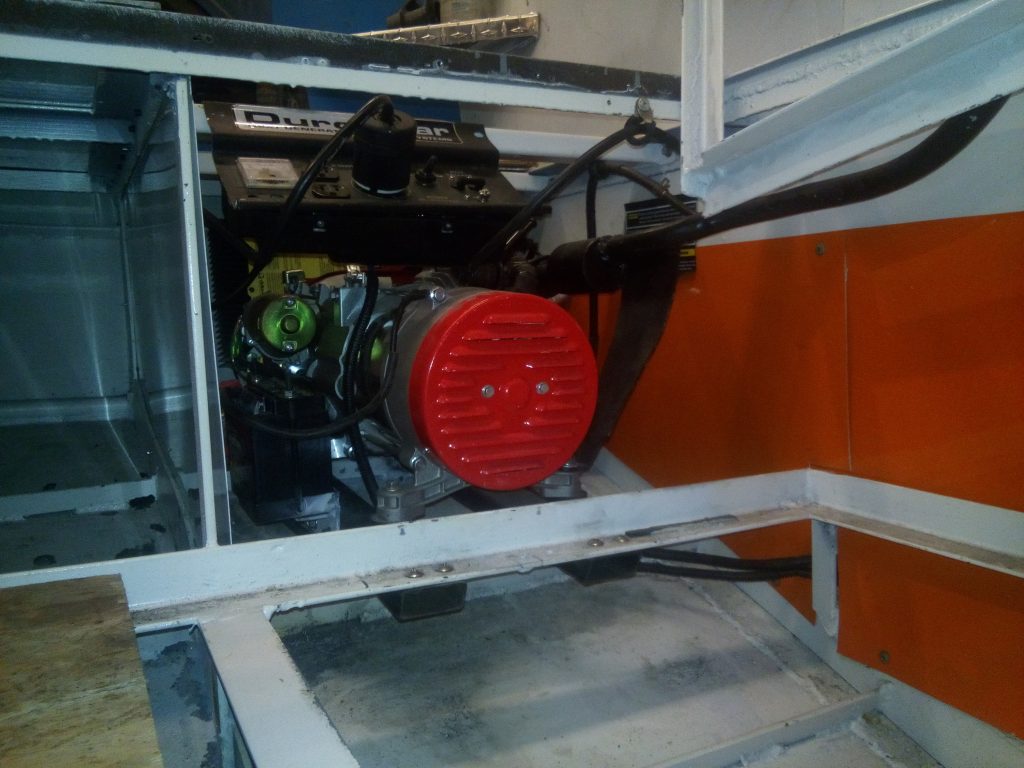
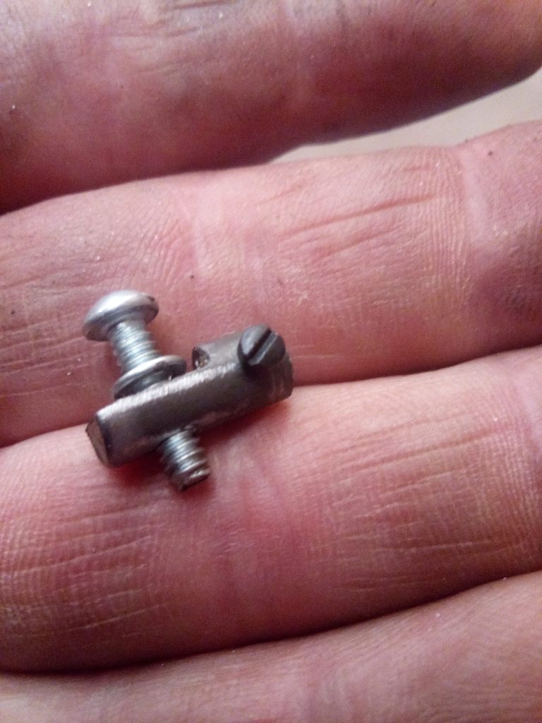
I removed the mufflers from the gensets, and started making my own that would fit in the boat. I might add, that with just the riser pipes with small expansion tanks in place, the generators are really loud... I am going to have to make sure the flex couplings and mufflers are really quiet when I finally get them fitted. The exhaust plumbing is only roughed out at the moment.
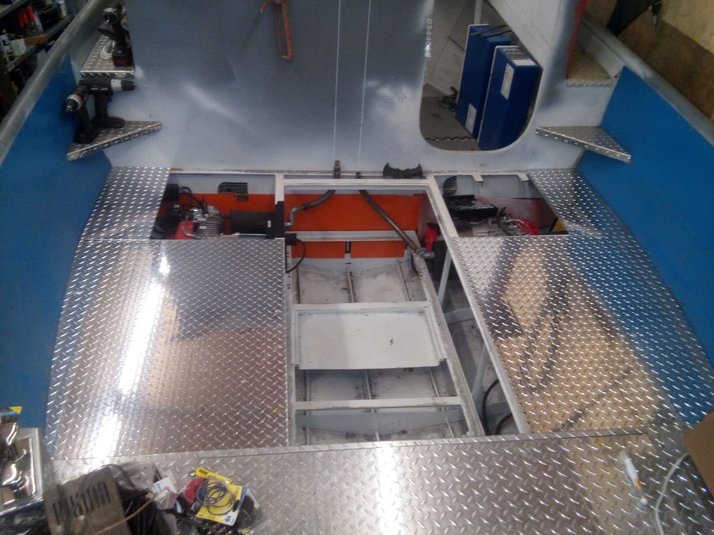
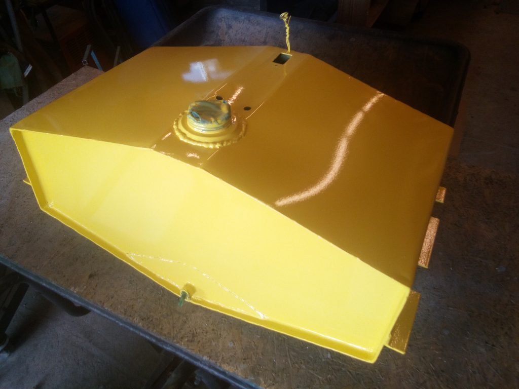
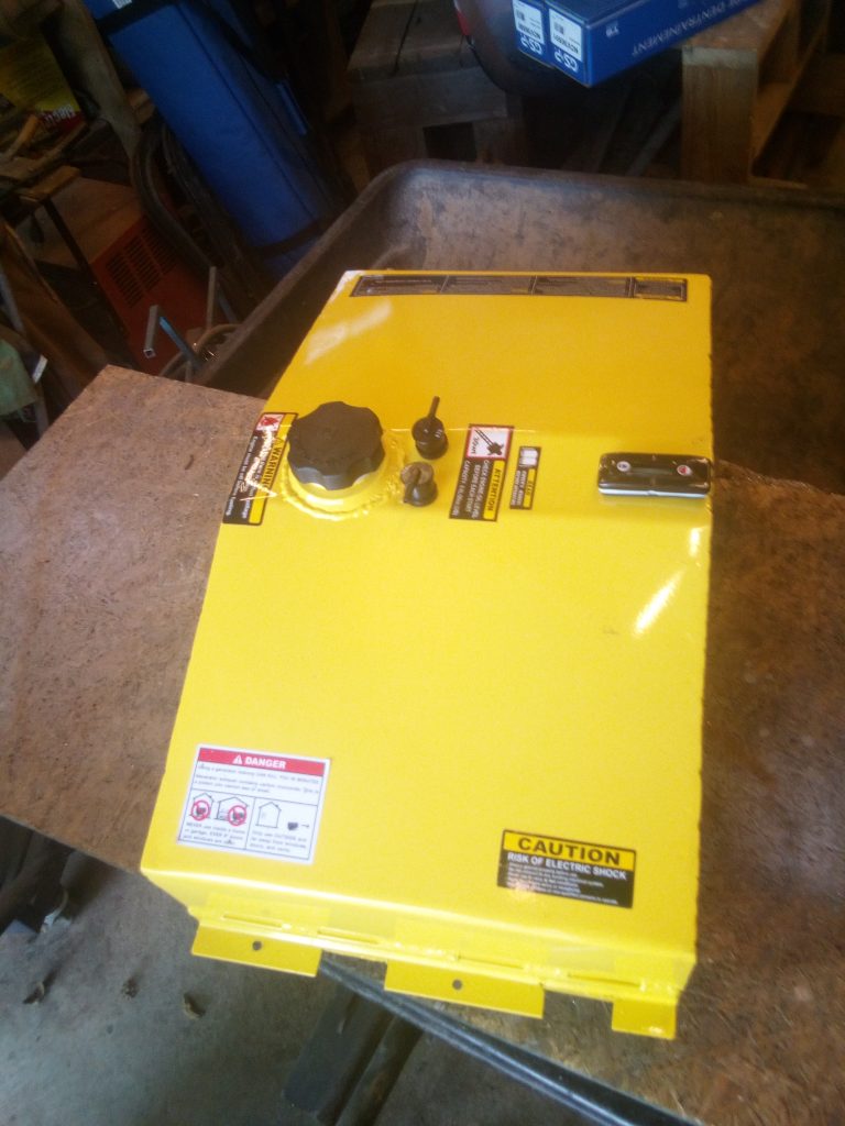
The fuel tanks were discarded to the back of the shop until I needed to rob them for their usable parts. I opted for what I computed to be about 12 gallons I think, with a bottom contour to closely match the bottom of the hull. The top of the tank is slightly raised for a USCG requirement having to do with slosh and venting when in rough water. I will know exactly what its quantity is when I fill it. The first fuel pumping plan was to use a pair of engine-driven oscillation pumps that run off the crankcase venting. I bought them, installed them, and primed the system up... The port engine started and ran for about a minute and a half before starving and quit. I never got the starboard engine to pop. Checked the system and found the pumps would not supply the needed fuel flow to the engines. So I went to plan "B". That is to get a low pressure electric fuel pump and a controllable pressure regulator and re-plumb the system. A month of waiting for parts and we are almost ready to try again. (I'll include pictures of the final plumbing in a future segment... Now on plan "C".
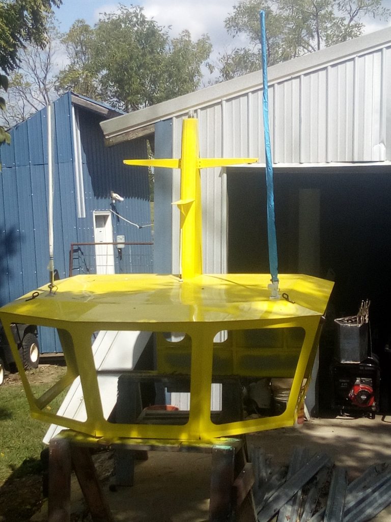
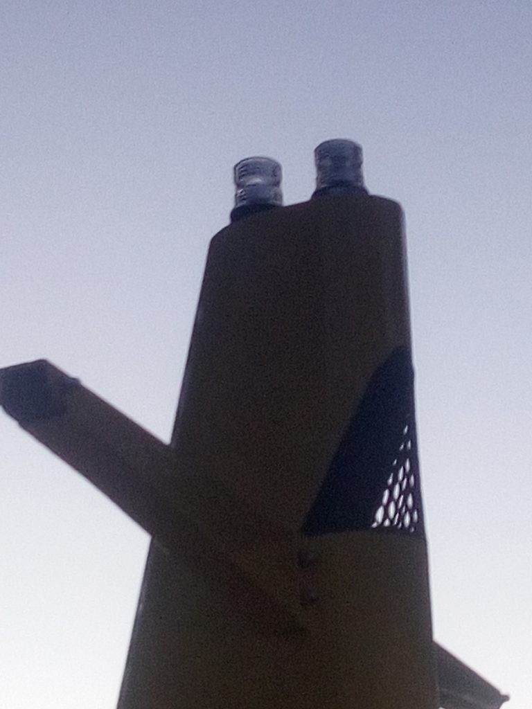
Meanwhile, I assembled the upper pylon and yardarm onto the upper wheelhouse and painted it. Wow, that Safety Yellow is bright. All the passers-by can see this little girl for miles. I guess that was the design. I started installing some gear like antennas and navigation lights in it too. I also started trying to figure out the interior. Ordered and received the interior lighting. I am planning on 12 volt LED components originally intended for a home, but I will not be using the included 120 VAC-12 VDC transformers. I have been holding off installing windows till I absolutely had to. It makes it easier to do the wiring and fitting of other pieces. I cut and rough-fit the polished stainless steel hand rails that will be for accessing the fore deck from the aft. (I'll include pictures of them in a future segment.)
I finished up more in the main deck plating, ordered venting grills, and tried to make contact with somebody, ANYBODY in authority to discuss things like USCG and ABYC requirements for venting, flotation, placarding, and a dozen other things that might be of concern to the prospective commercial buyer.
(There is no publicly acceptable picture to convey my utter frustration...)
(Caution, rant approaching...)
I am here to tell you that the local Detachment of the USCG would not so much as even consider talking to me about it, much less come and see it. They even REFUSED to come look at the build in my shop! I never got a call back from the ABYC reps. I contacted the Missouri Water patrol (an arm of the State Police), and they were aware of it, but had no interest in the requirements (or even leaving their offices), except to tell me that they would inspect it when it was done to see I had it secured well to the trailer,... that it had all the proper paperwork for registration,... and they might, ... come inspect for the required HIN (Hull Identification Numbers) placements... I later got a call back saying that no visit was planned. I will have to trailer it to the office in the middle of Springfield, and park it in their tiny parking lot for the obligatory inspection. I am seeing a real disconnect here in the area of requirements and application and conformity.
This is all included here with this explanation. Several months back during the Summer sometime, there was a commercial duck-boat accident in Branson, where it went out, loaded with Pax, in stormy conditions, poorly fitted for emergency gear, and a whole bunch of tourists lost their lives when it sank in the storm. I do not want to have that kind of thing happen to any of my builds. I can not control the usage, maintenance, etc. But I can at least build it safe in the first place. Then I can have a clear conscience when I hand the keys to the new owner. So I am just a bit perplexed as to the "commercial requirements" that may apply. This is of no interest to the builder that is going to use a boat for personal use, I.E. a "pleasure craft." Needless to say, I will be making sure I have some safety gear more than for a personal boat.
Now back to our regularly scheduled boat building programming...
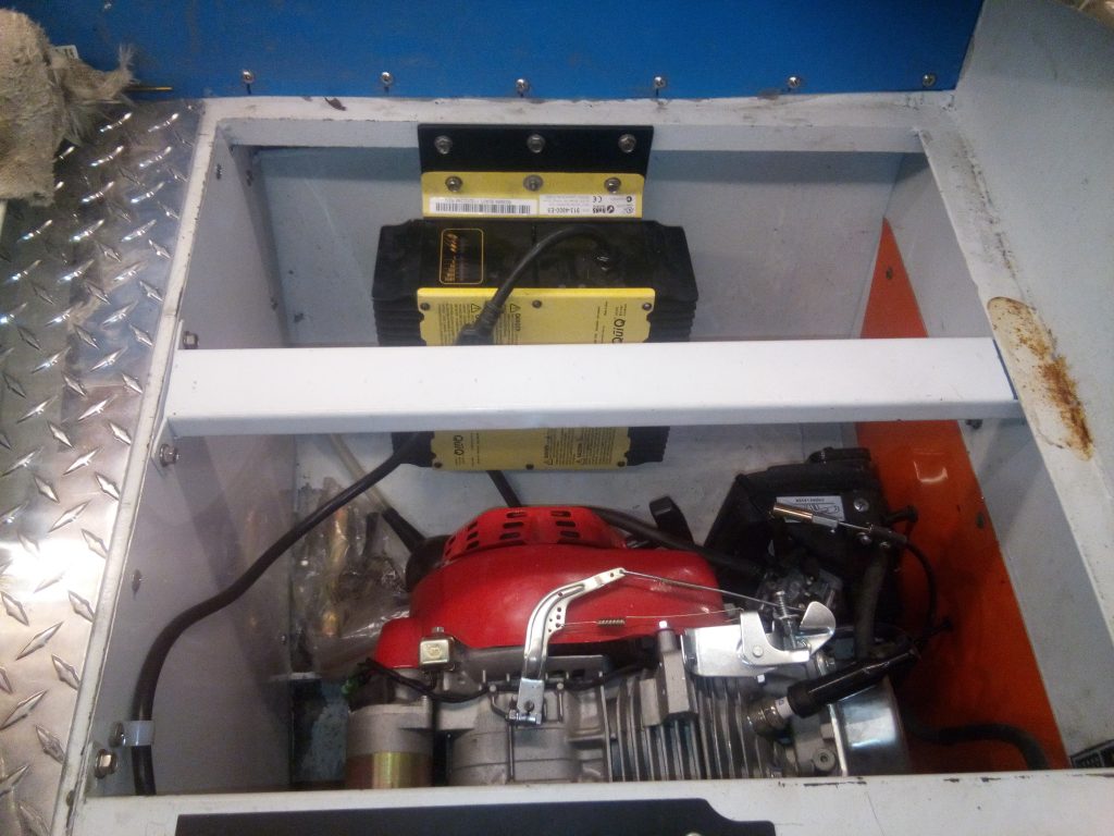
I installed dual AC-to-DC battery chargers next to the gensets, and shortened the power cords to fit the application.
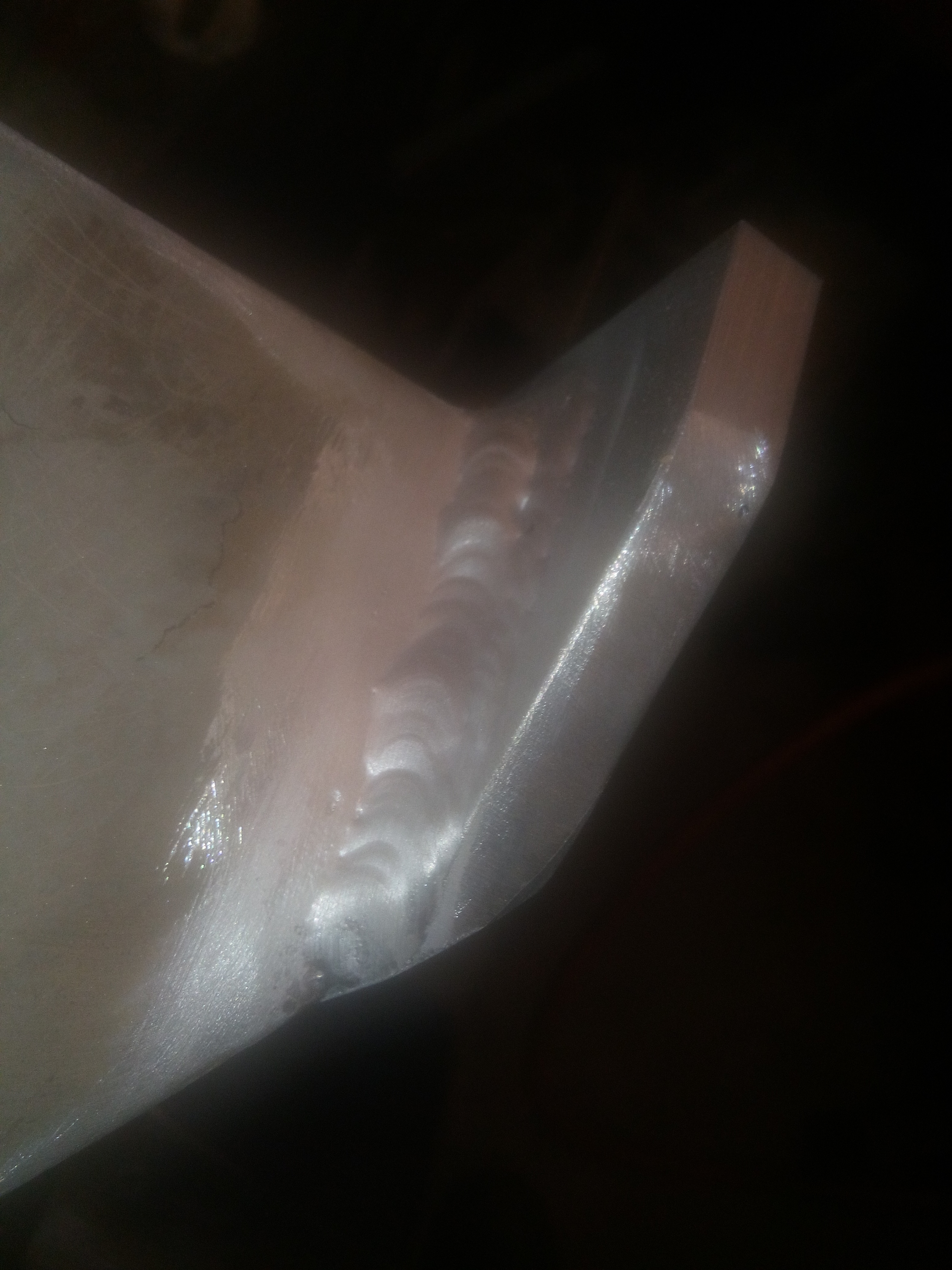
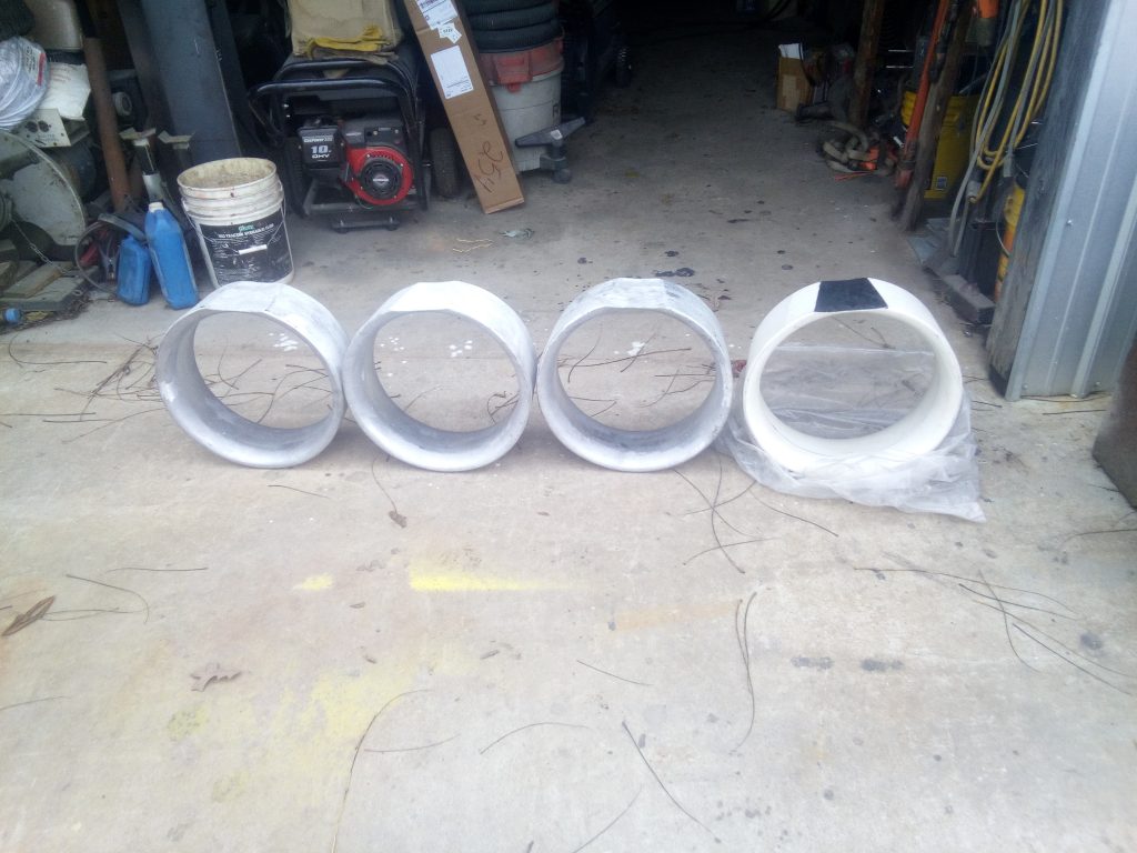
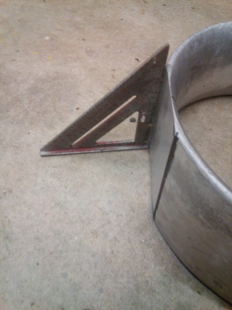
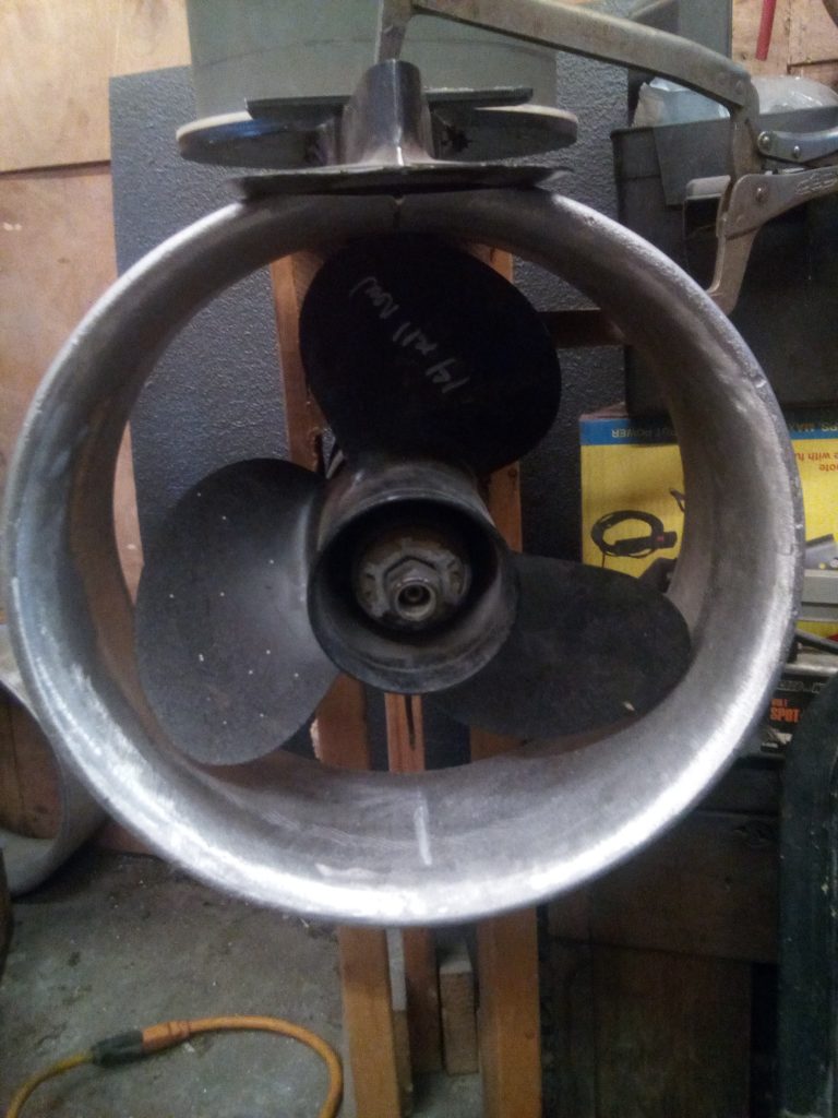
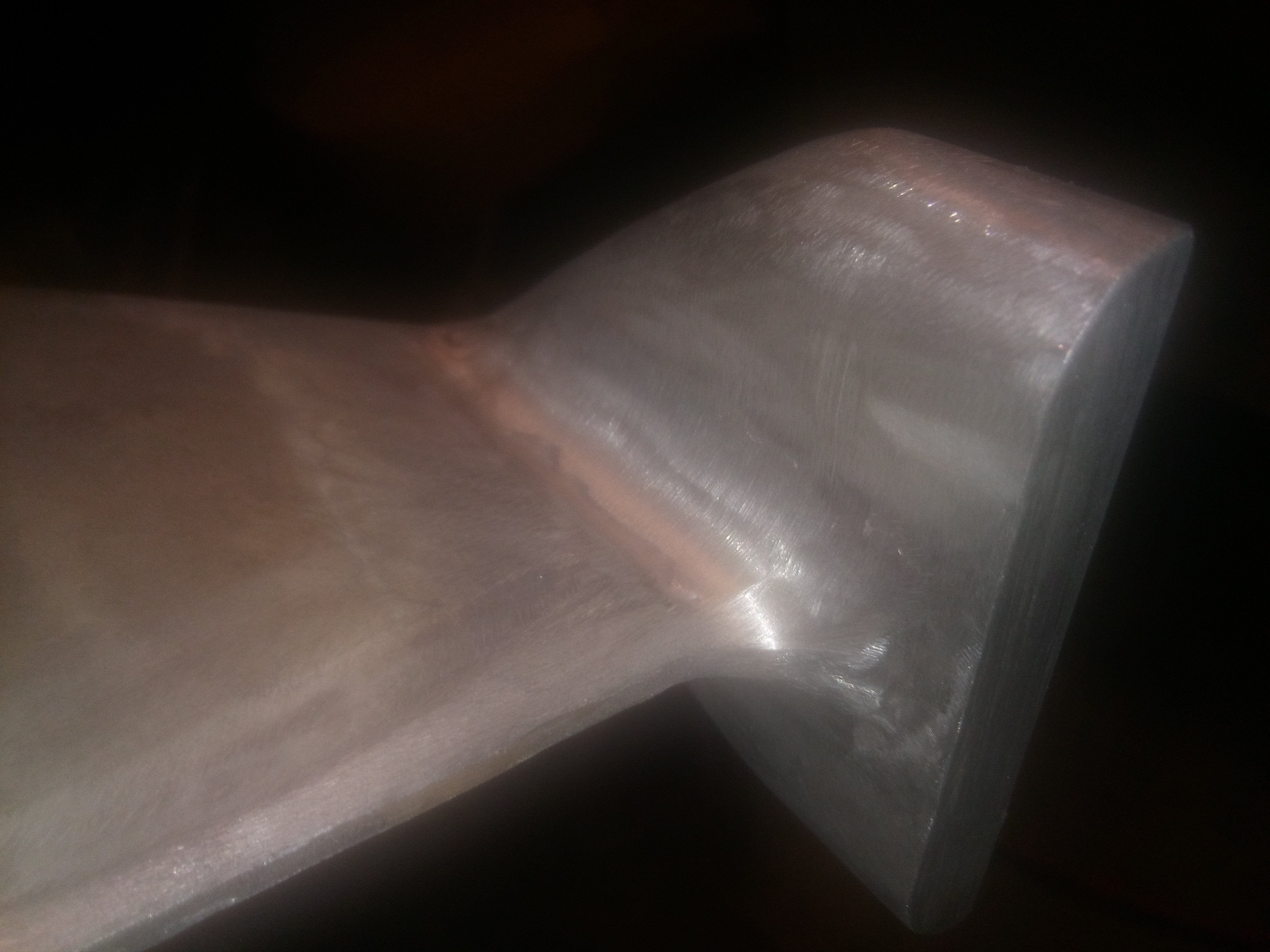
I got the aluminum duct castings (prop nozzles), from the foundry on the 29th of October while on my way to visit my son's family in Idaho. Started finishing them and blueprinting them to the drive assemblies on the 8th of November. This operation is tedious work, and is quite time consuming. There is about 1/8" clearance around the props on these things, so they will create the desired thrust. That requires the hand fitting to each lower anti-cavitation plate, and then added bracing to the skegs, etc. When the drive castings for the outboards are made, they are not as precision as one might think. For now, I'll show a preliminary fitting of the duct, but when the installation is complete, I will revisit this element of the build.
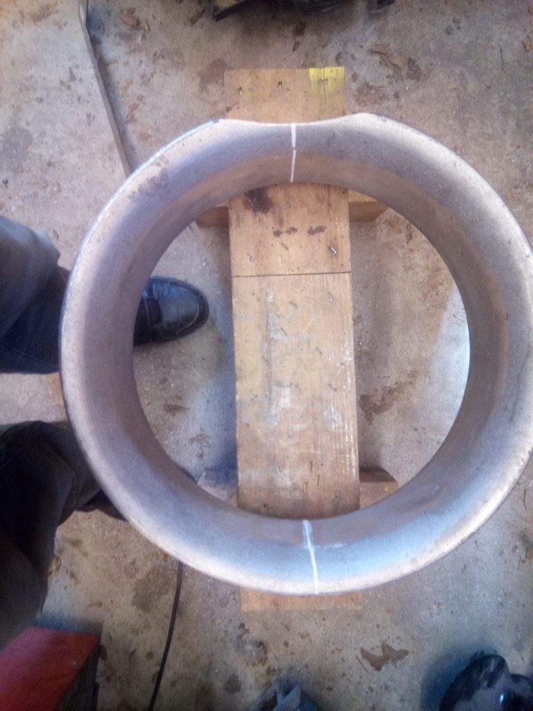
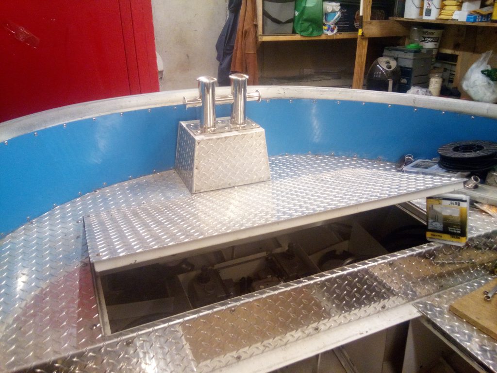
After building and installing it, I decided to remove and reshape the aft, center pedestal for the twin bollard, so the motor hatch would open a bit better. I have an agreement with the shop where I have all my aluminum welding done. I get a better price if when I bring in parts, that they are "fit-in" jobs, and no real rush. Took about a week to get it re-welded. I then re-sealed, and installed. Works like designed now.
I got the first small bilge pump installed with the float switch and mounting bracket and all pre-wired out to the electrical raceway.
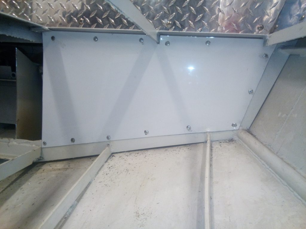
It seems like I do more removing of several parts, to install another part these days. That was the case with the firewalls fore and aft of the gensets. Installed aft firewalls for gensets. For USCG regs, I found it would be better to wall them off, and provide separate ventilation for them, for both cooling and fume mitigation. I got some 4' x 10' sheets of 18 Ga. (.040) aluminum sheet for this task. I also cut and installed firewalls just ahead of the motorbay.
Since the battery banks will be sealed AGM cells from NorthStar, I won't have to provide fans and venting for them. However, I may put some in for cooling. That is it for now, Hope all have a very happy and peaceful Christmas and superb start to an exciting New Year.
Since my last installment in the middle of December, I have continued to work on several systems and, ... wiring. I did not like my first iteration of the aft, center hatch cover for the aft battery bank. So I removed it and built one with an easier way to seal it from splash on the decks.
I finished the finish-filing of the mating faces of the drives and mounted them, hopefully for the last time before I can get it wet. I had to do some additional mods to the skegs of the drives to receive and hold the ducts securely.
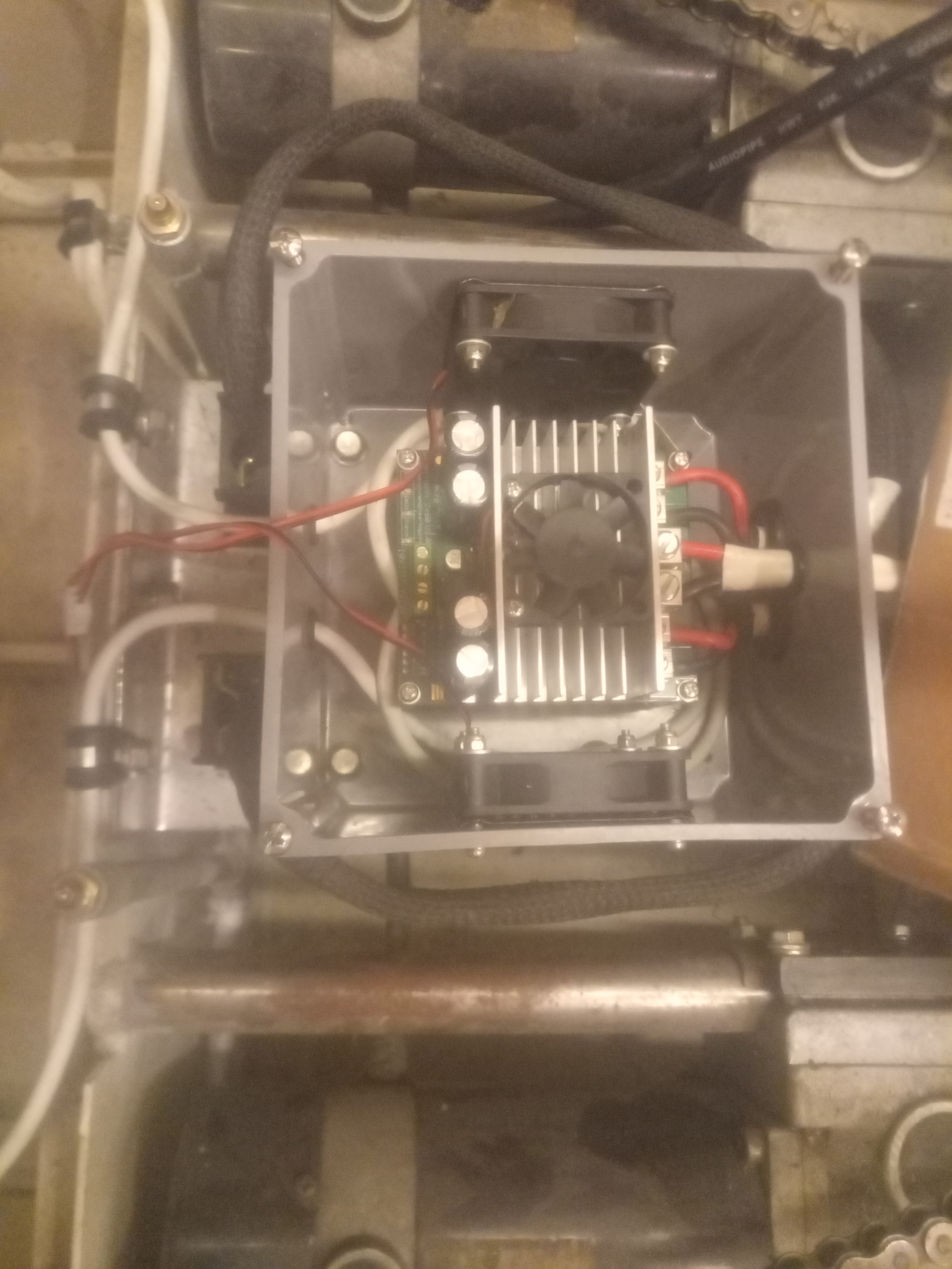
I finished the installation of the steering systems and installed the steering controller I got from Dimension Engineering. Wiring is almost done at this installment. It is not hard to install, I have had to spread my time between my farm work, helping neighbors, fixing my own equipment when it quits, .... and building a house, and doing church work occasionally.
60 amp steering controller
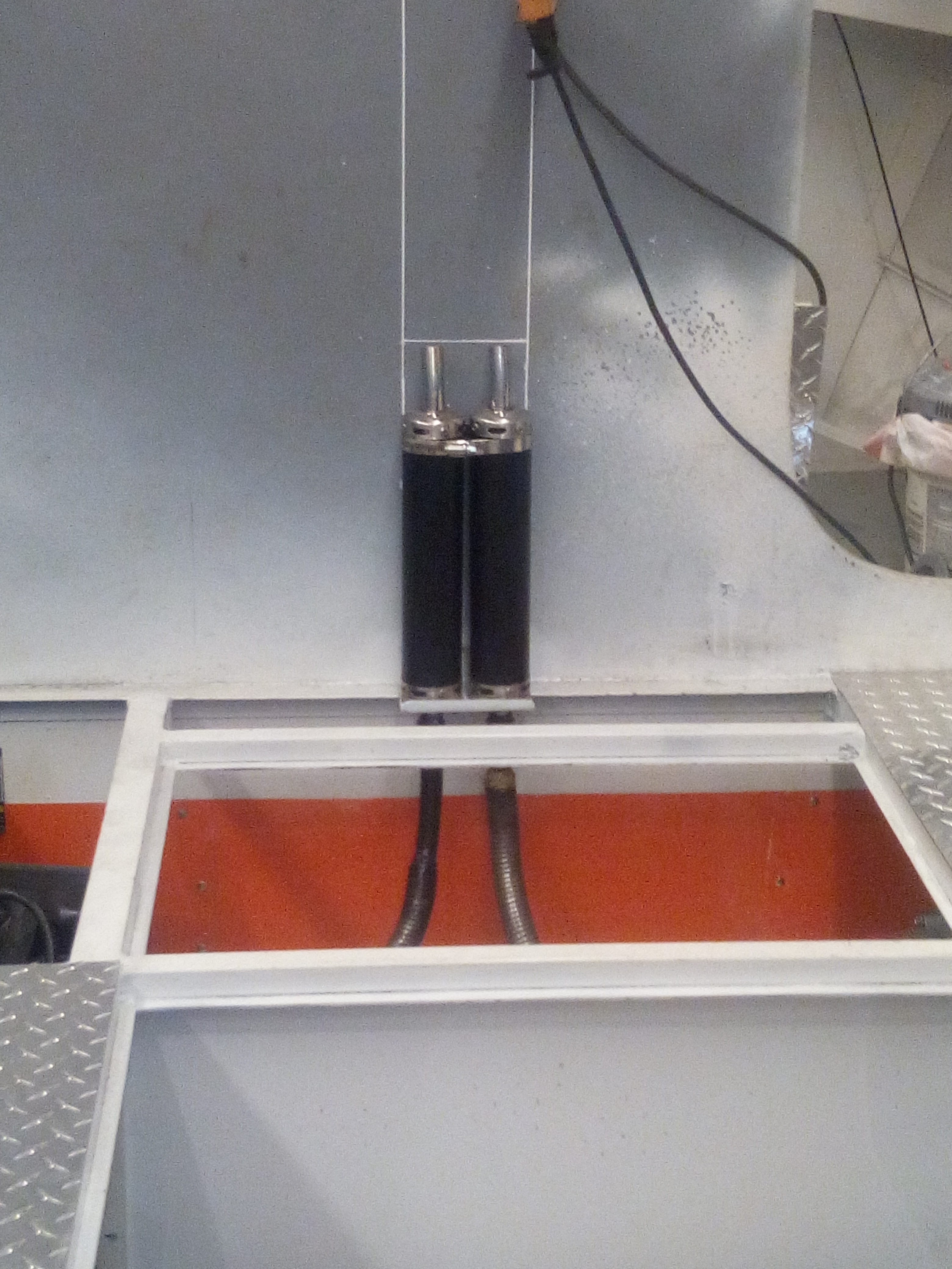
I got the gensets all in and the first iteration of expansion chambers for the exhaust was, ... not good. So I took a crash course in muffler design, as the original generator mufflers are worthless. I made some new mufflers 2/3rds the size of the stock ones that actually worked quite well. I then supplemented them with 50cc scooter resonators each. I got the combined exhaust and engine noise level down from well over a hundred each, to 73 db, combined, standing in the boat, in my enclosed shop, (with the doors open of course). Stacks will go up the back of the pylon and exit near the yard-arm. I haven't finished the stacks yet. I am waiting till I actually mount the upper wheelhouse onto the boat.
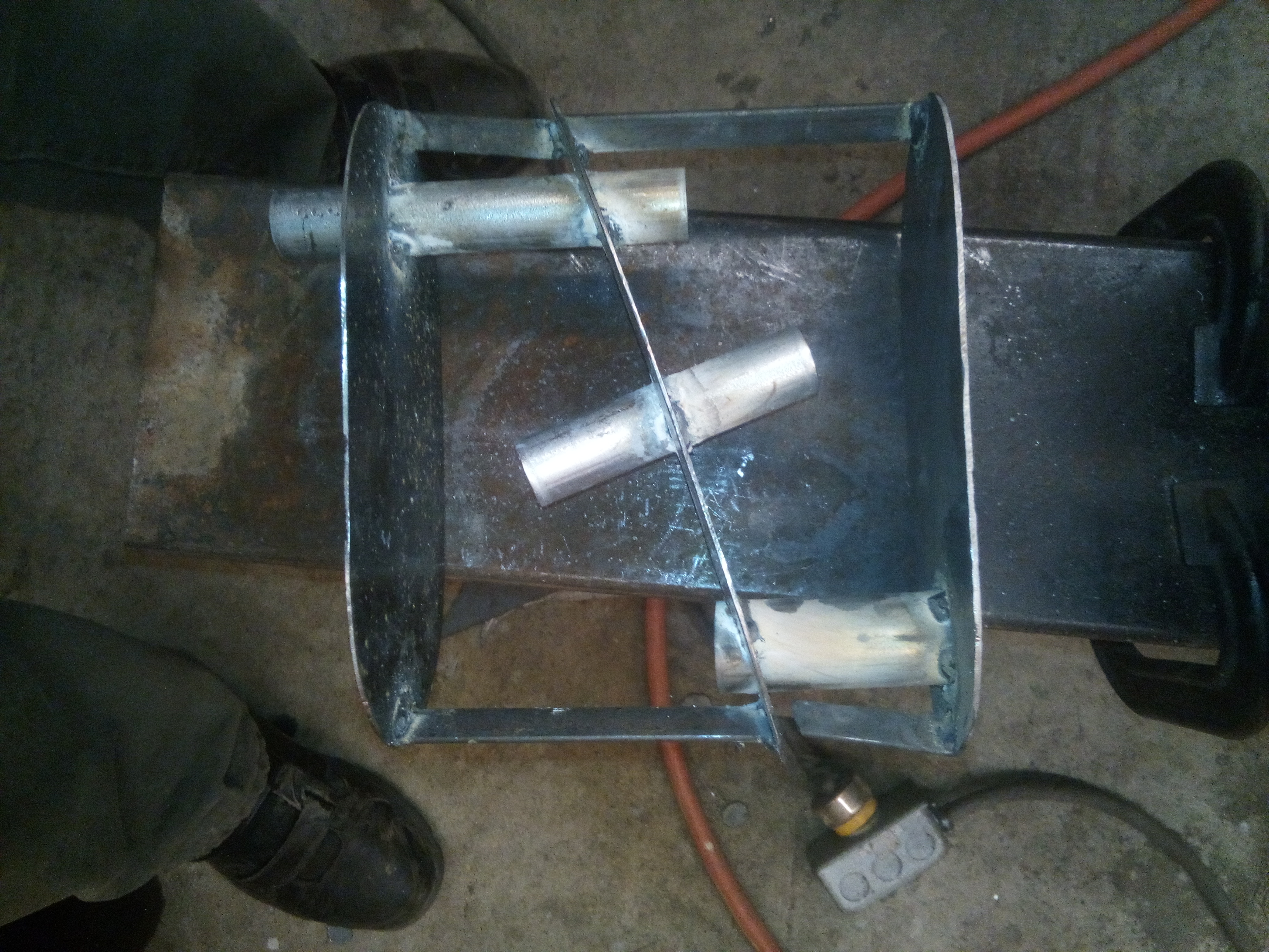
Constructing the mufflers
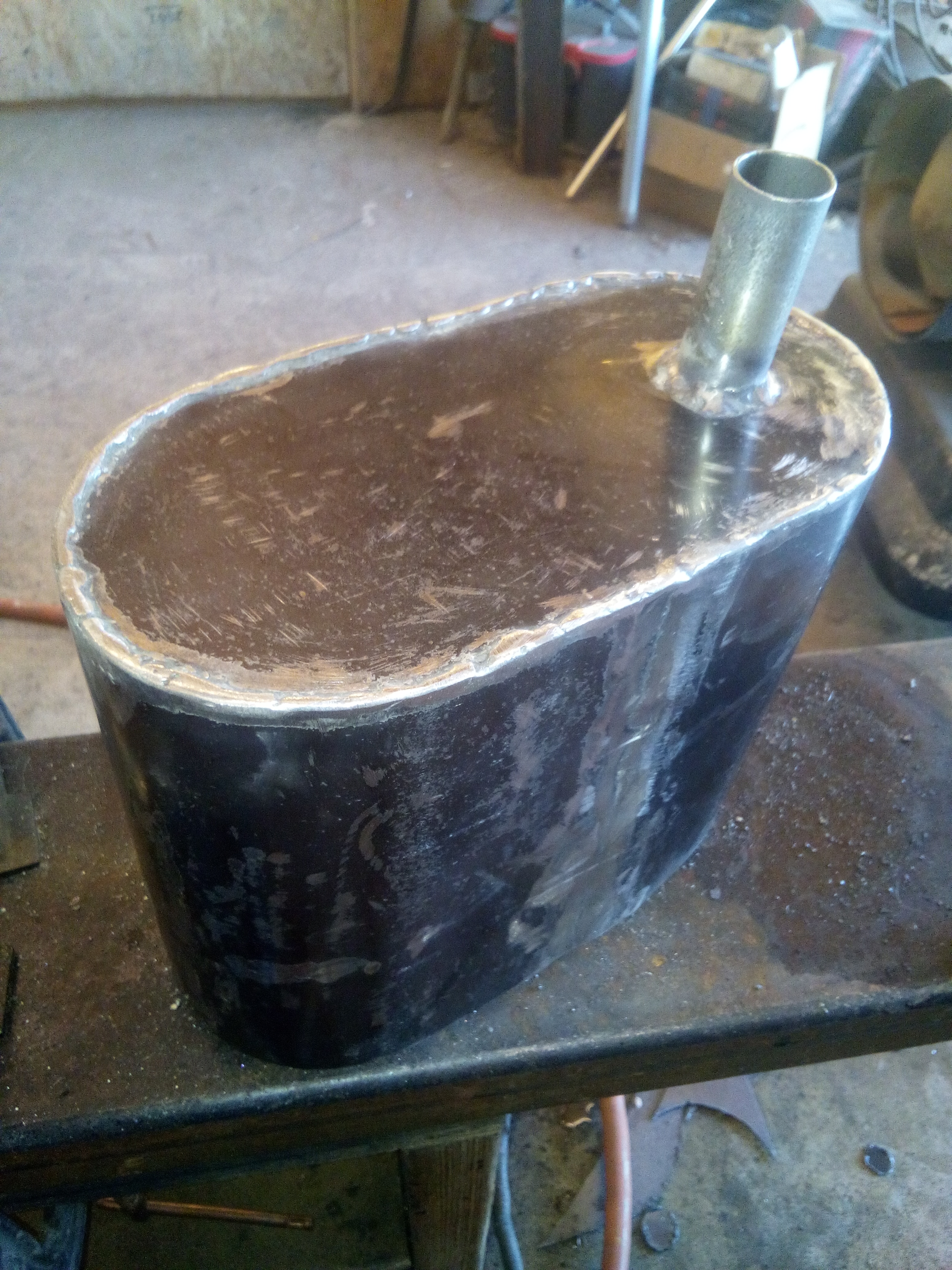
Homemade muffler
Resonators
I also added a string of fans in each gunnel over the chargers and gensets that fill the cavity between frames #4 and #5. There is a rack on each side, of 9, 2 1/2", 24 VDC computer fans. They are the thicker, longer life 1" ones. I chose 24 volts to spread out the loads on the 3 different battery banks and make it easier to make them 2 speed.
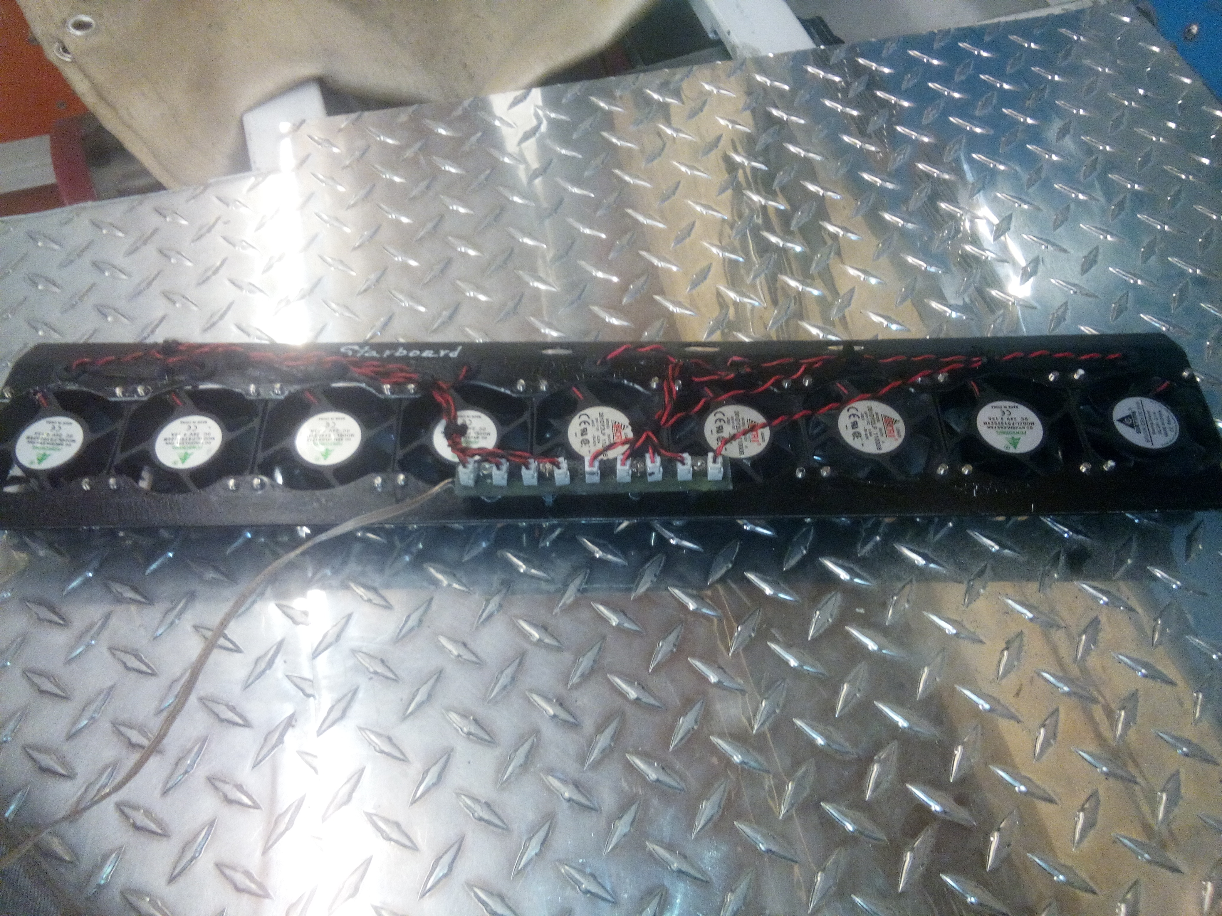
String of 9 fans
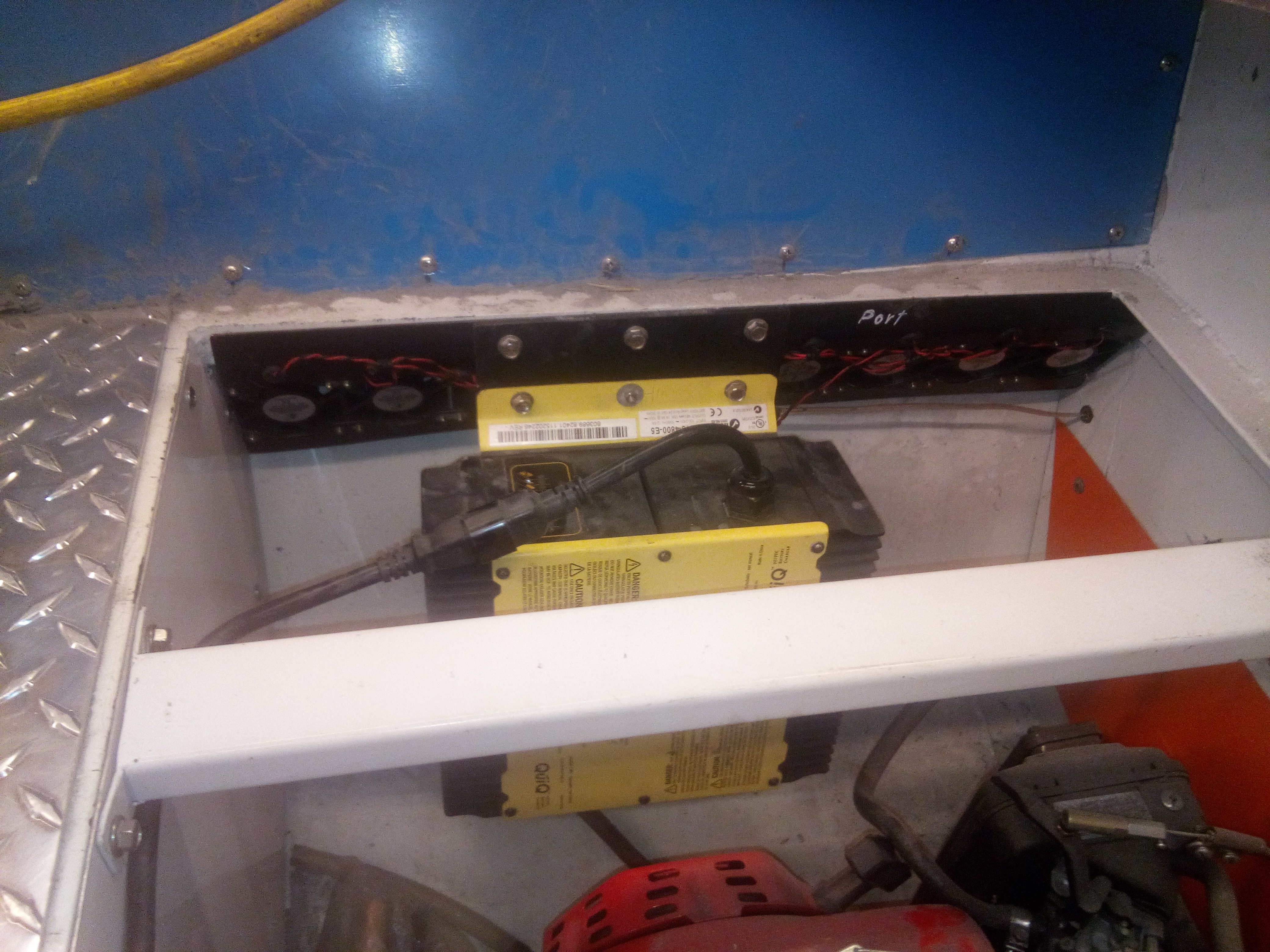
String of fans installed
I have filled the center instrument panel and am wiring all the instruments. I used a Greenlee hole punch sized for the round instruments I borrowed from my aviation repair toolbox, to cut clean holes in the panel.
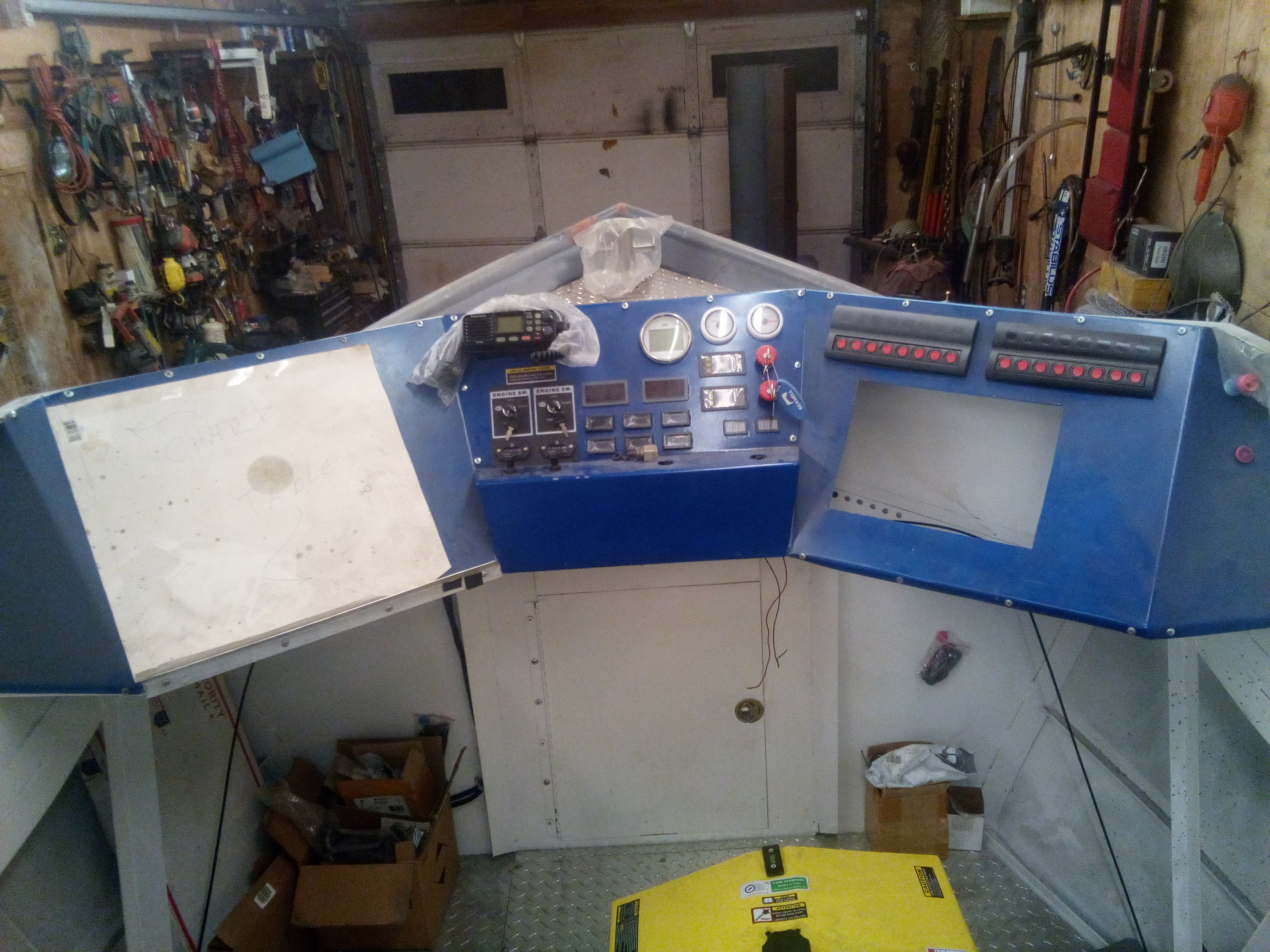
Instrument panel
I had a place in Springfield, Rose Metal Products, laser out some 20 Ga. stainless sheets that I broke into the fan mounting boxes for the drive motors.
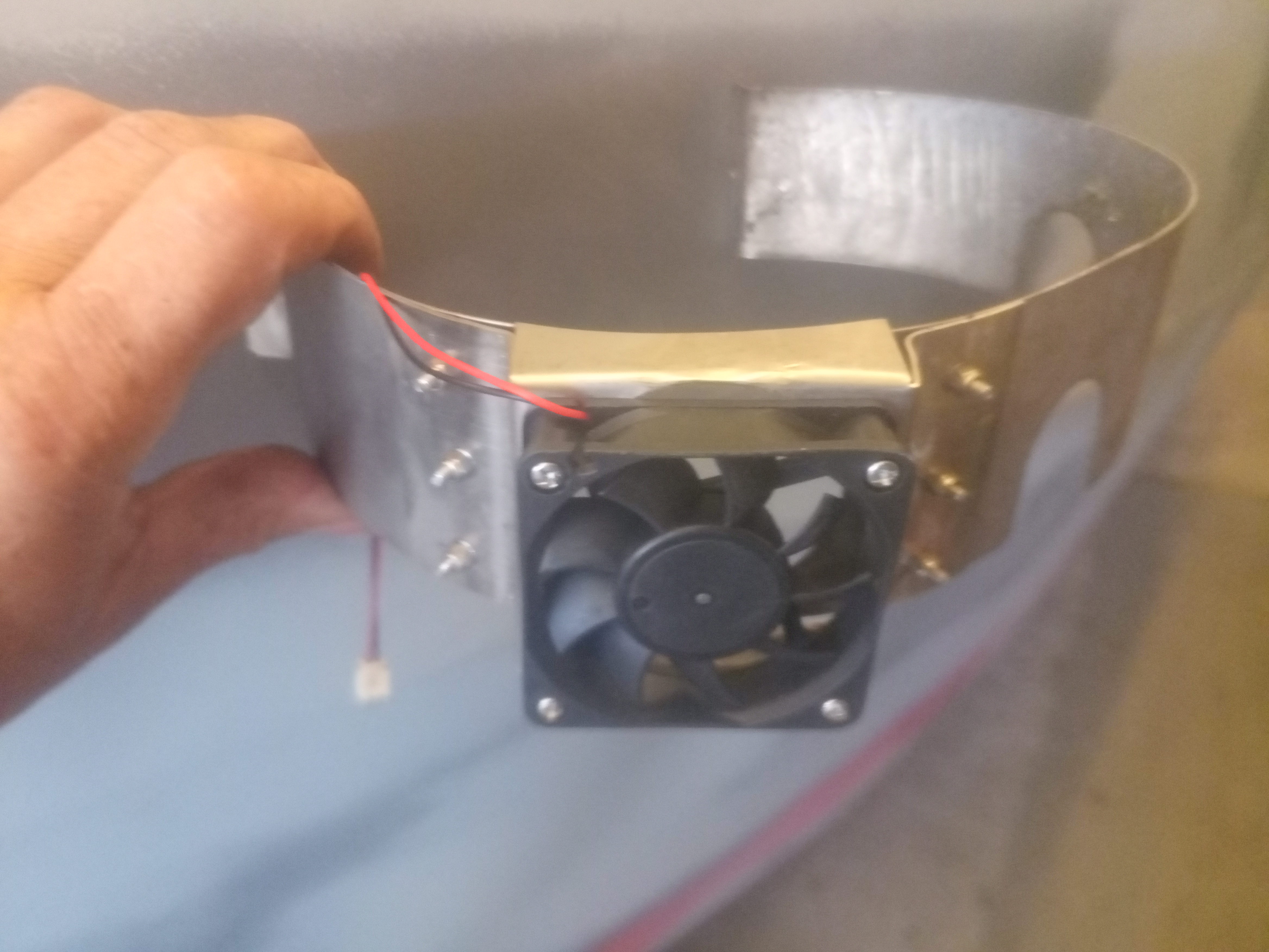
Fan mounted on fan box
After struggling with getting the correct fuel flow with the bilge-mounted fuel tank, as well as having several discussions with a couple of marine engineers and a couple commercial boat builders, I jerked out the tank and opted for a pair of modified metal jerry-cans in the gunnels. In the end, it as easier to install, less complicated for venting, and simpler to have fuel onboard.
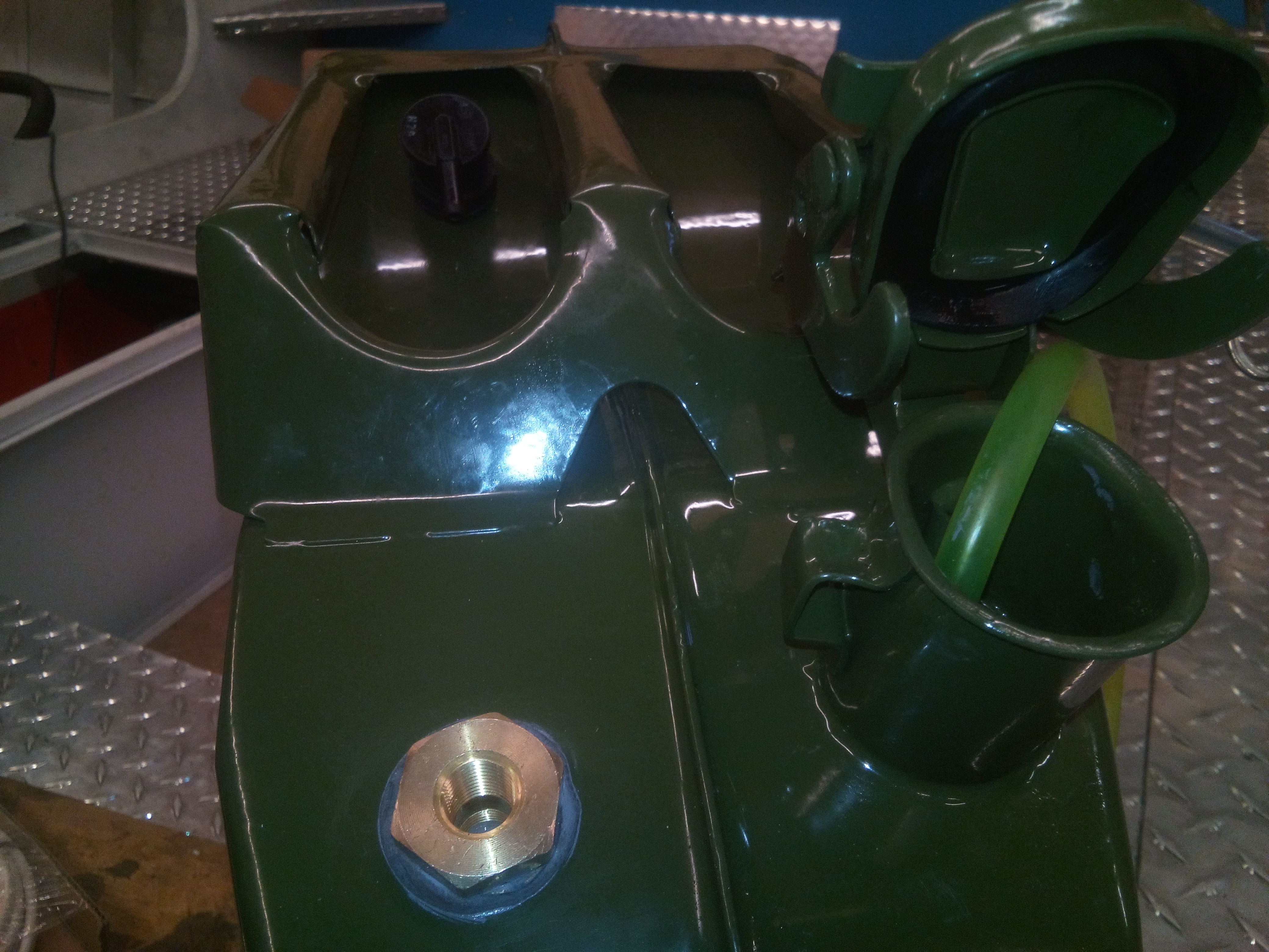
Jerry can conversions
I still had to make fan banks and plug strips so if an individual fan quit, it would be easier to replace, (simple bolt-in and plug-in).
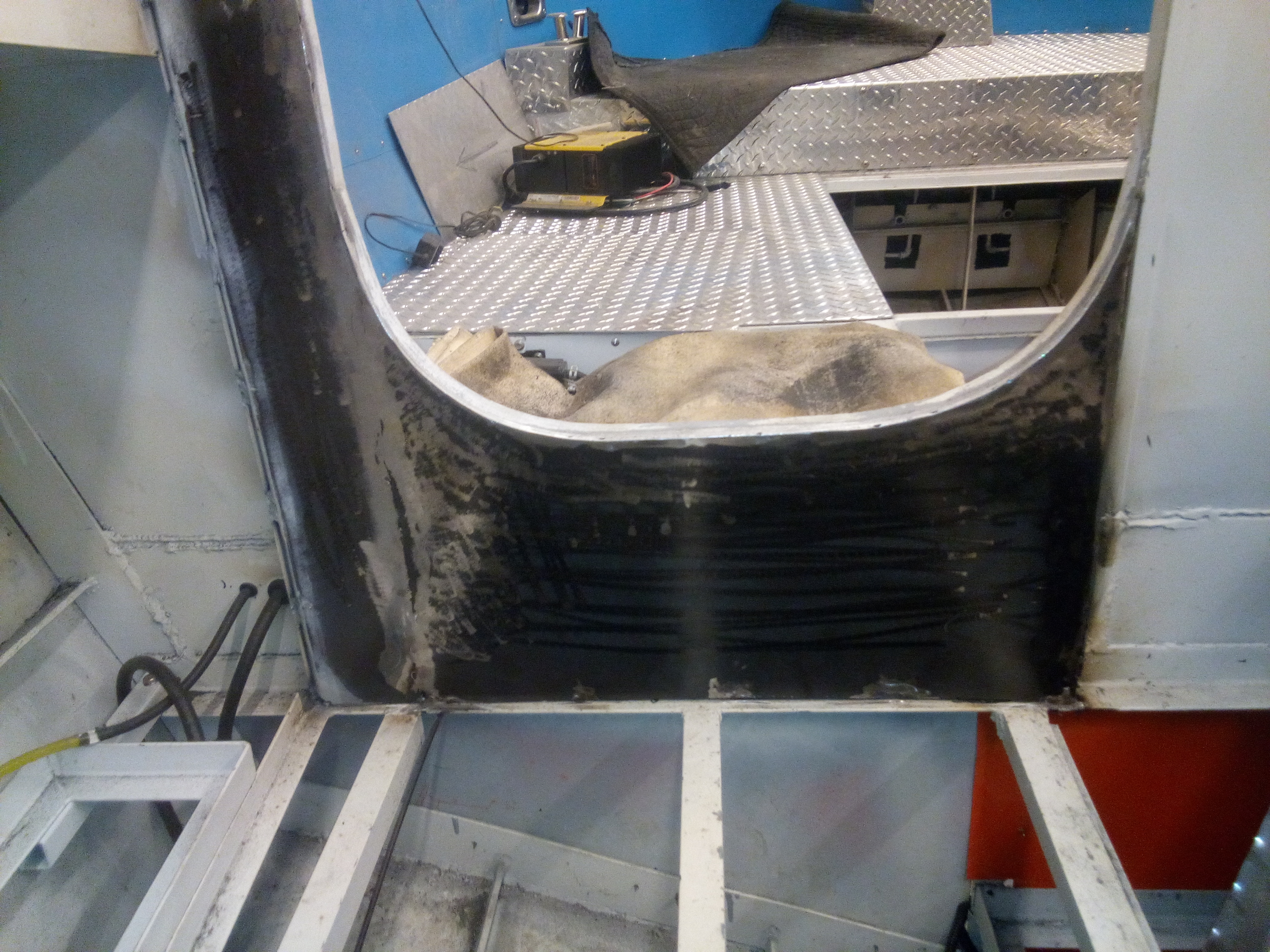
I started steel skinning the aft bulkhead of the lower wheelhouse and foam-filling the cavity for sound.
Inside bulkhead
In May/June, I took the upper wheel house to Monett Glass in Monett. They cut and got tempered the front and back tinted glass, and installed them. The side units are yet to be installed and have a sliding section in them.
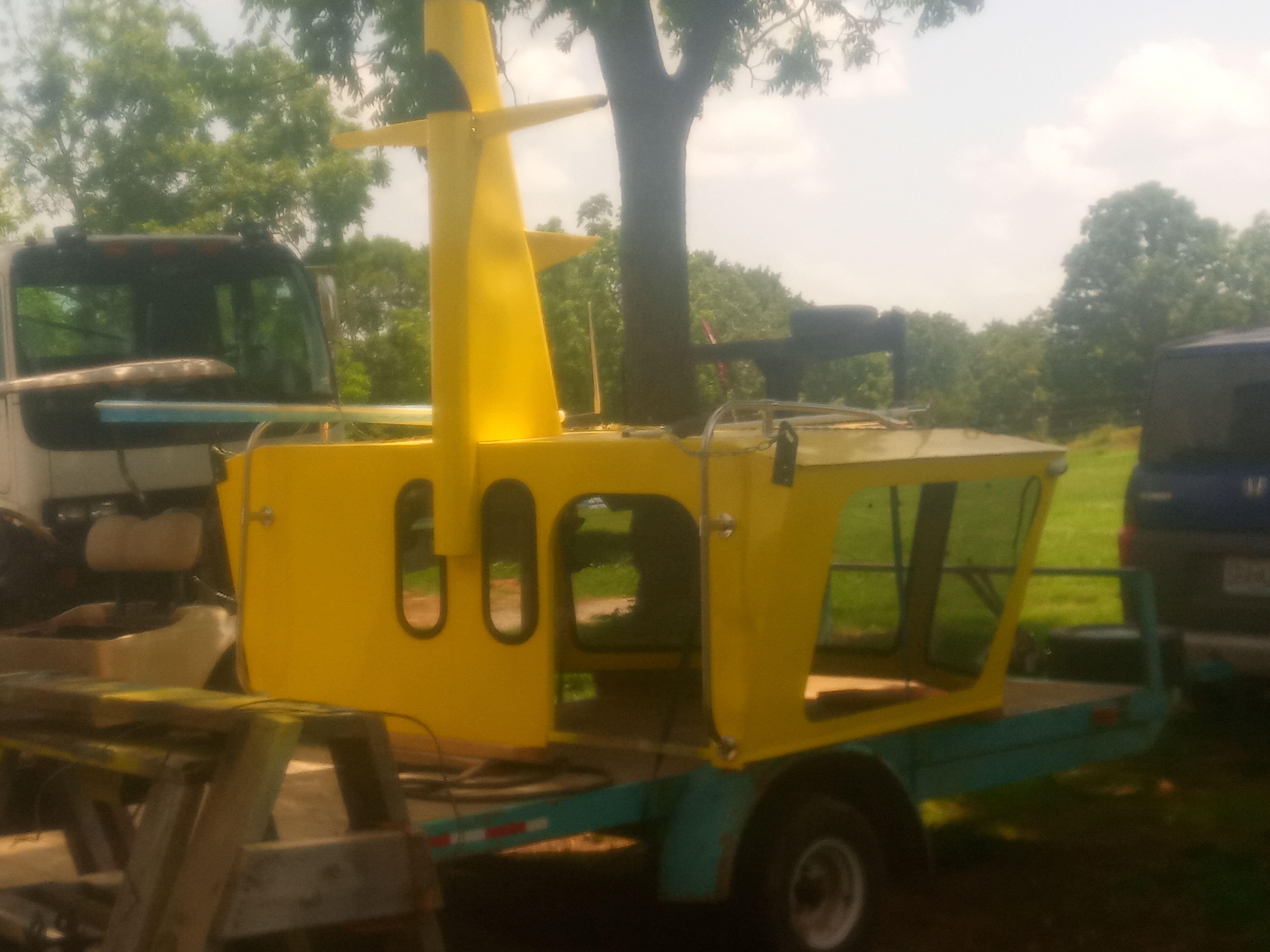
Wheelhouse aft
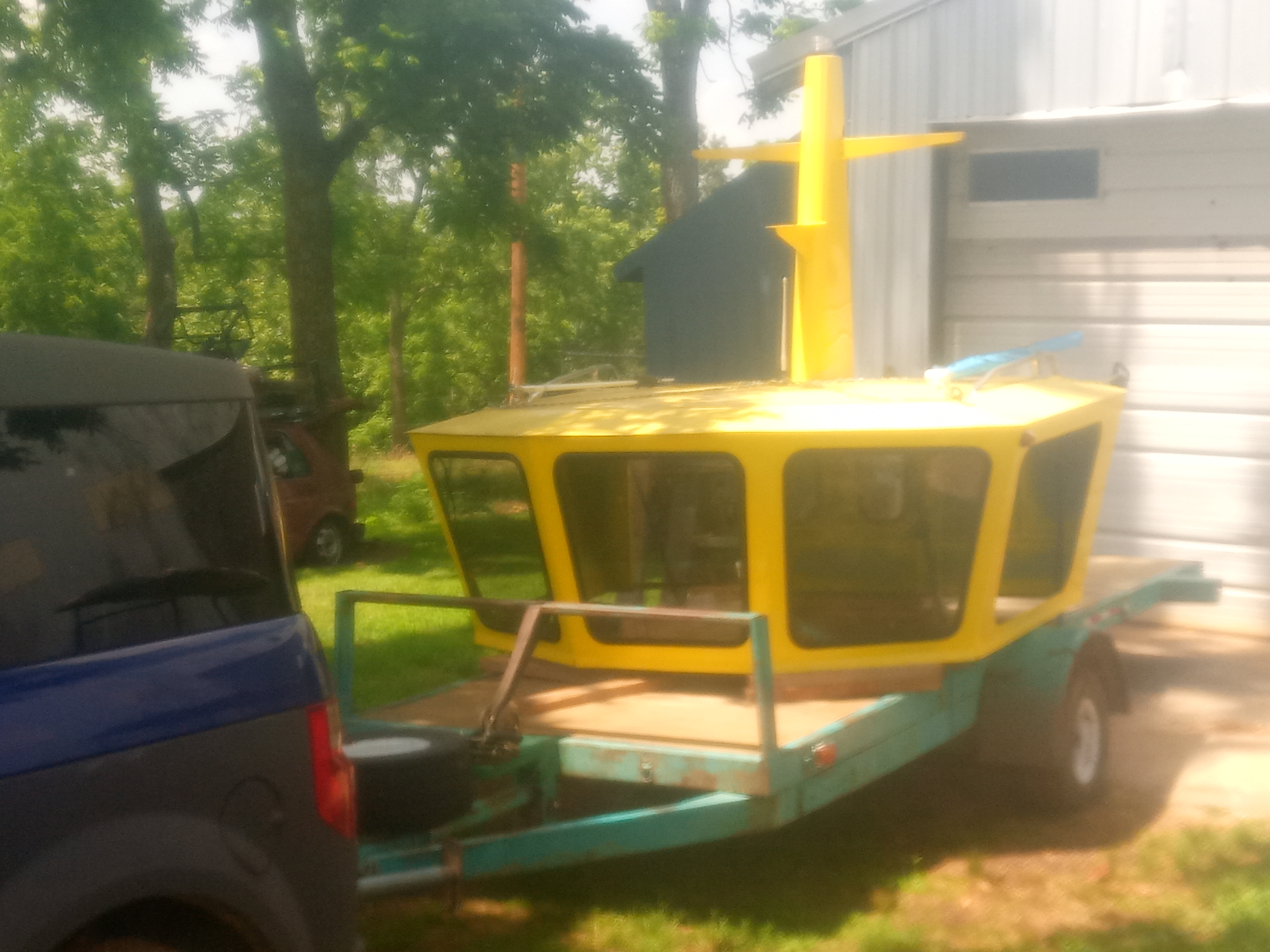
Wheelhouse aft
I also started doing the finishing, sealing and bolting down the deck plated that I could work around.
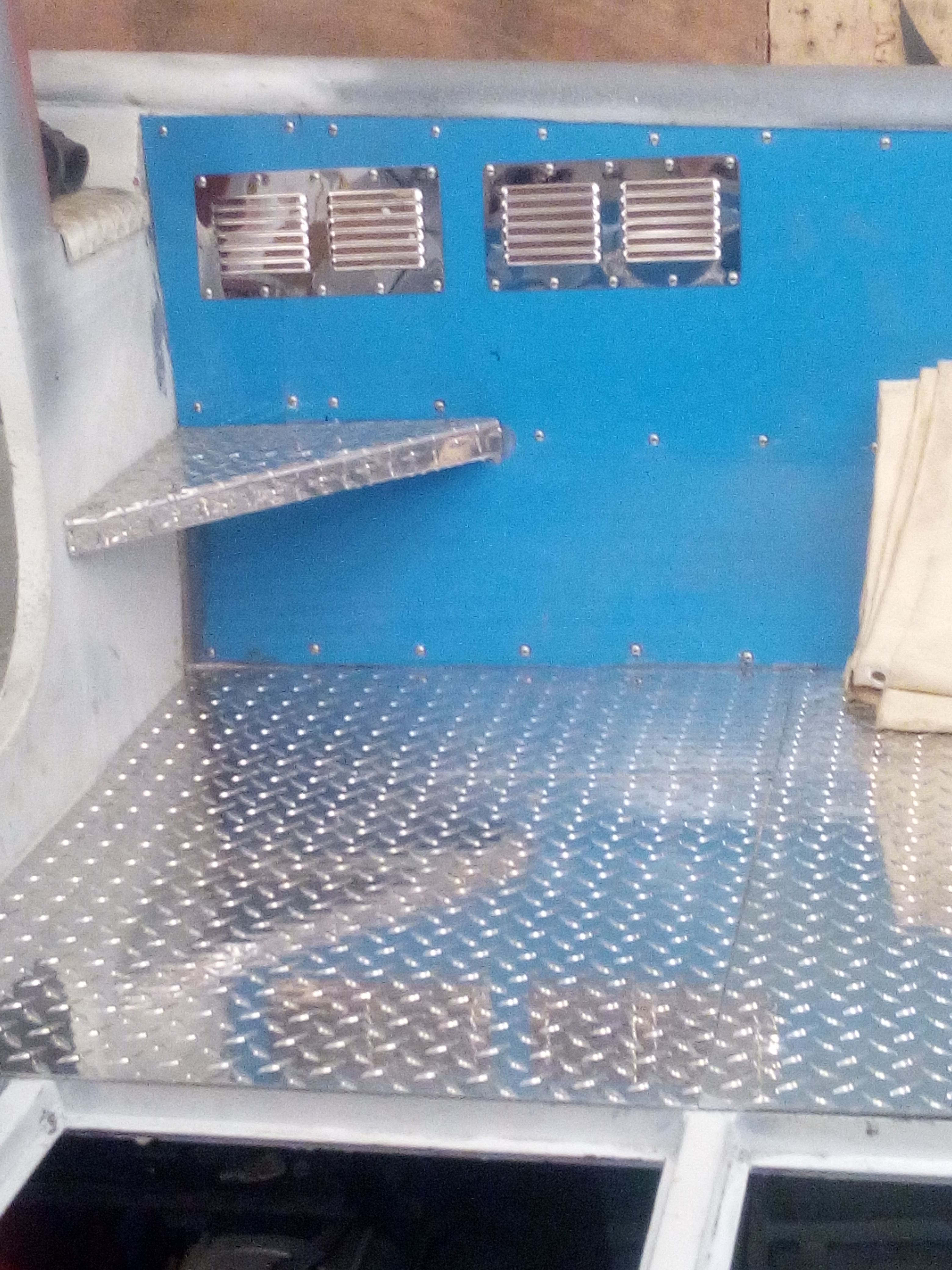
Deck plate with corner step and bilge vents
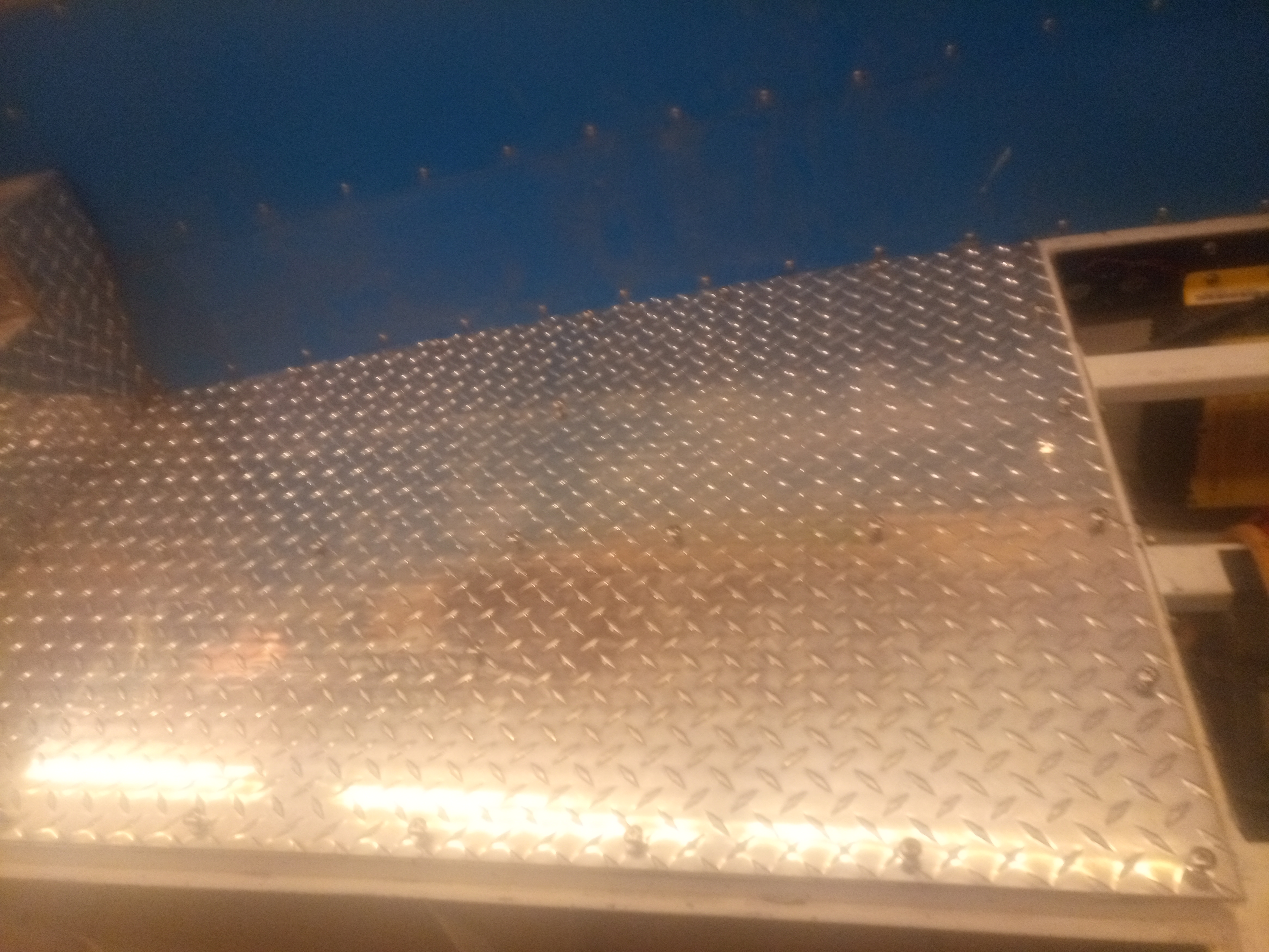
Deck plate glued & screwed
Then I made some wire trays from some 22 Ga. galvanized steel studs. They worked great.
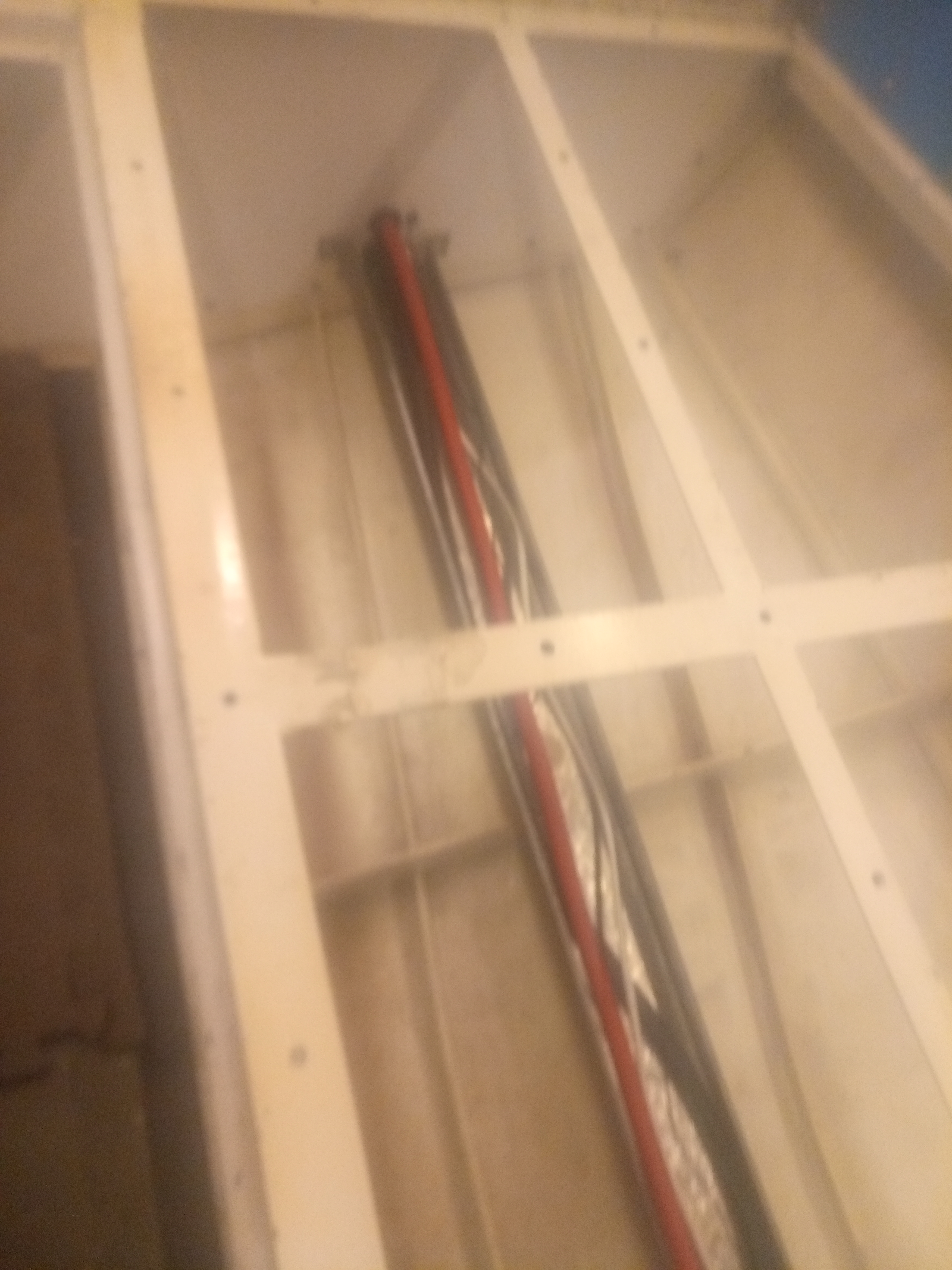
Wiring tray and installed wires
I ordered and installed the over-sized drive cables, but am looking into a slip ring idea to simplify the system and reduce wire fatigue from constant flexing.
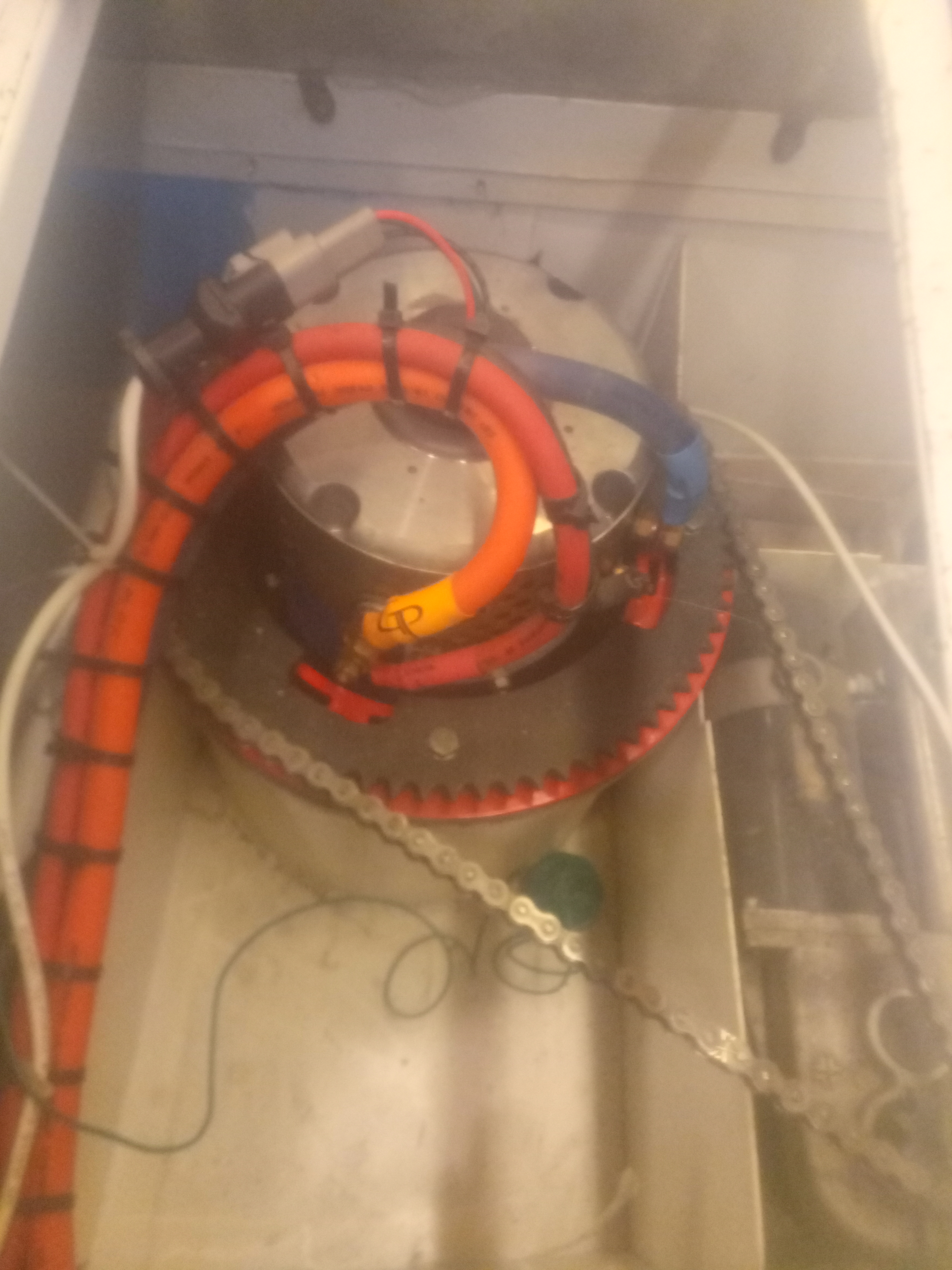
Motor cables over starboard motor
As the weather begins to turn nasty outside in a couple months, I expect to be making more postings. The wiring needs to be right, and so the tedious work of making plug connections, and anchoring wires and bundles to the structure, moves on at a slow, steady pace. It doesn't look like much work has progressed, but I spend several hours a week in the bilges and under the consoles making and sealing connections.
I finally ordered and got in the twin roof-mounted, remote controlled, spot lights.
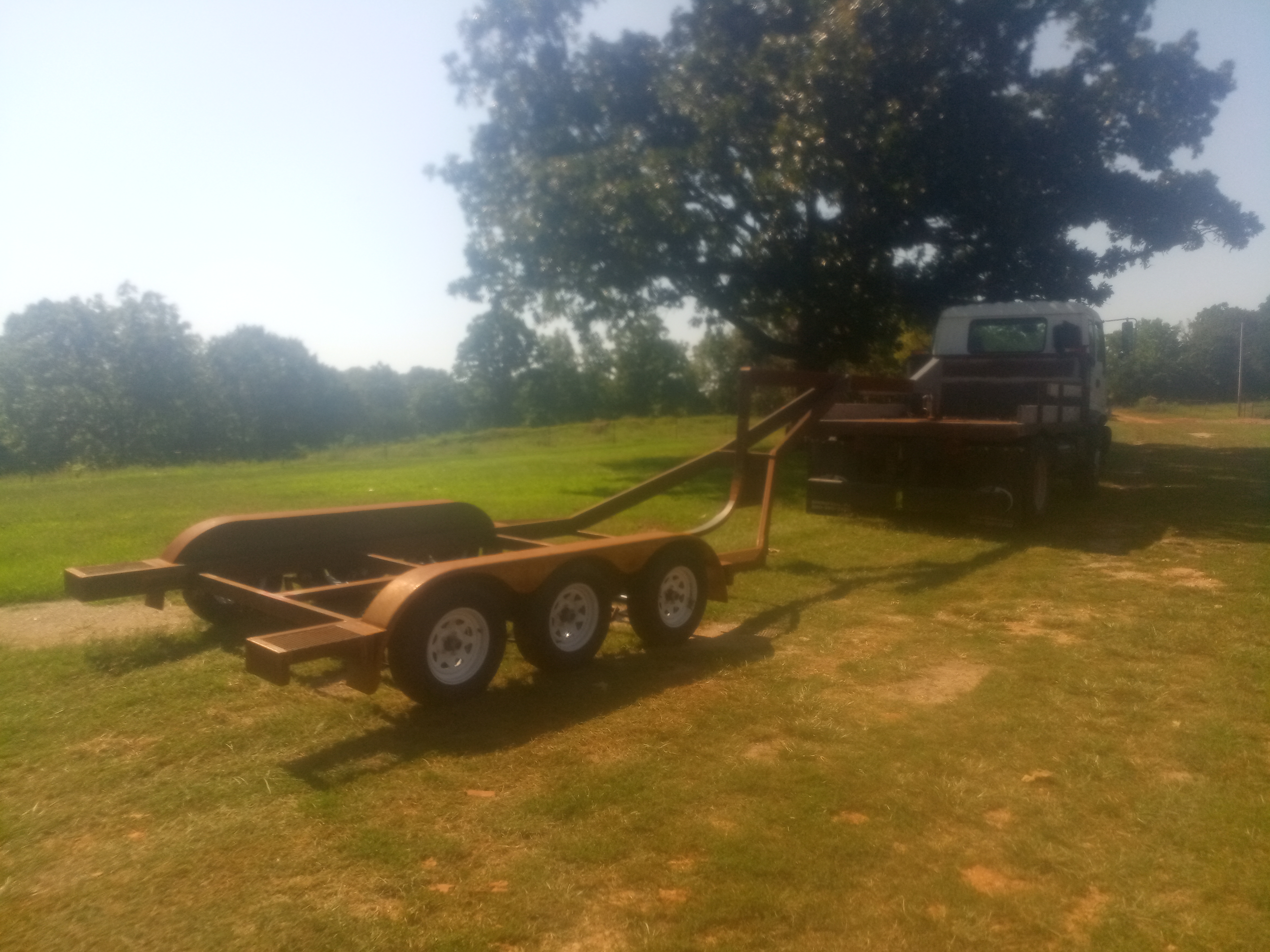
Also this summer, I had to stop working on the tug for a month so I could make the trailer. After several winters of watching boat loading/launching fails on YouTube, I made some critical choices when it came to the trailer build. Since I have had extensive experience in trailer design and building, I decided to make a special, purpose-built trailer just to haul this little tug. With the expected load of 5,000 pounds of boat alone, I felt I needed to not settle for one of the commercial offerings and take the time to design one special.
Custom Trailer
I wanted 125% axle capacity which meant triple, 3500# axles and all braking type. I wanted smaller tires, so I opted for 10 ply, 205 x 75R14".
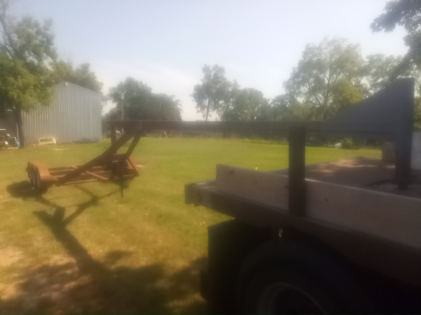
I wanted to minimize the chances of undersized tow-vehicles being able to haul the load and making an expensive mistake at the ramp, so I decided to make it a goose-neck hitch that only a larger pickup or semi could pull.
Gooseneck extended
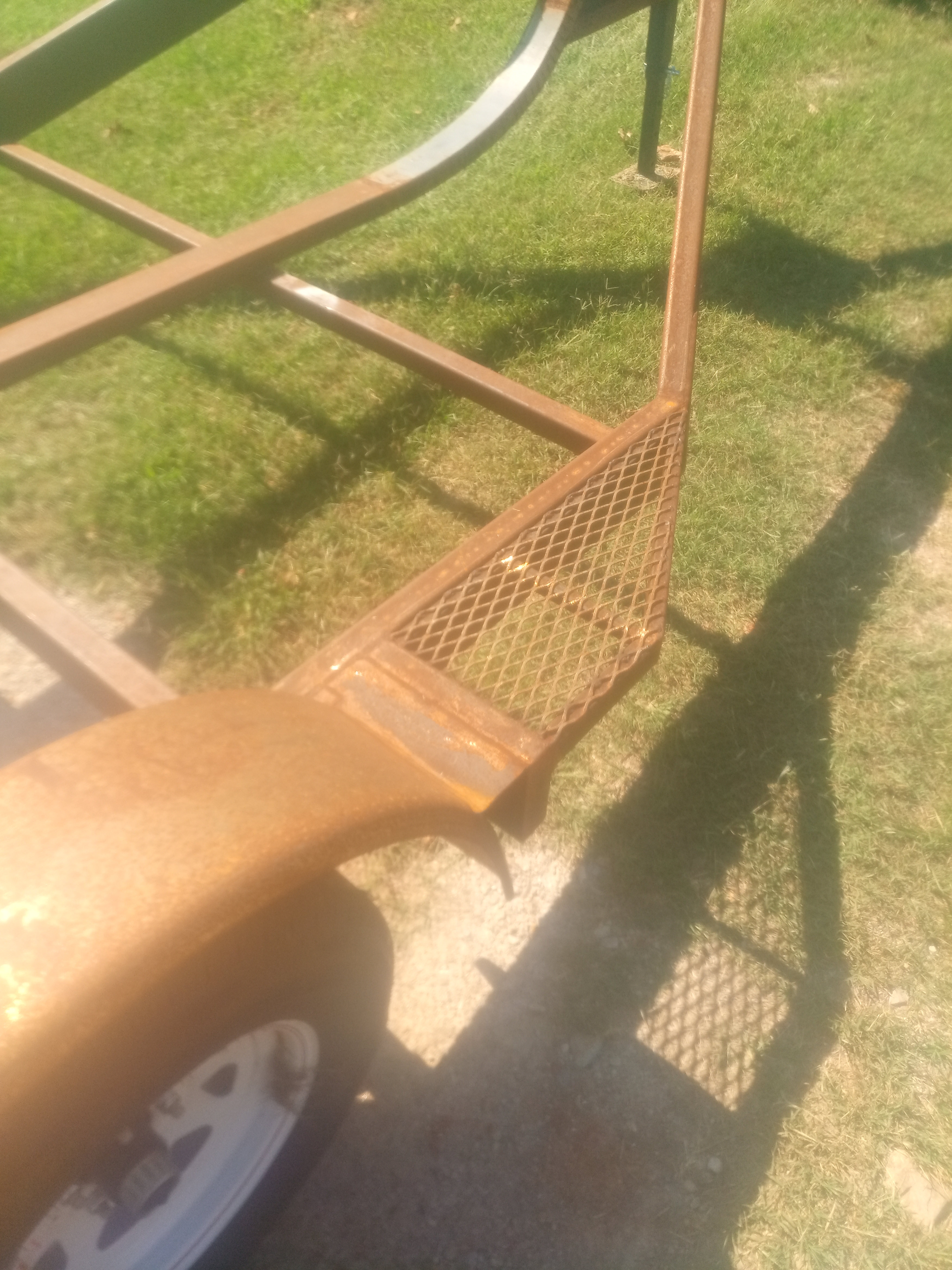
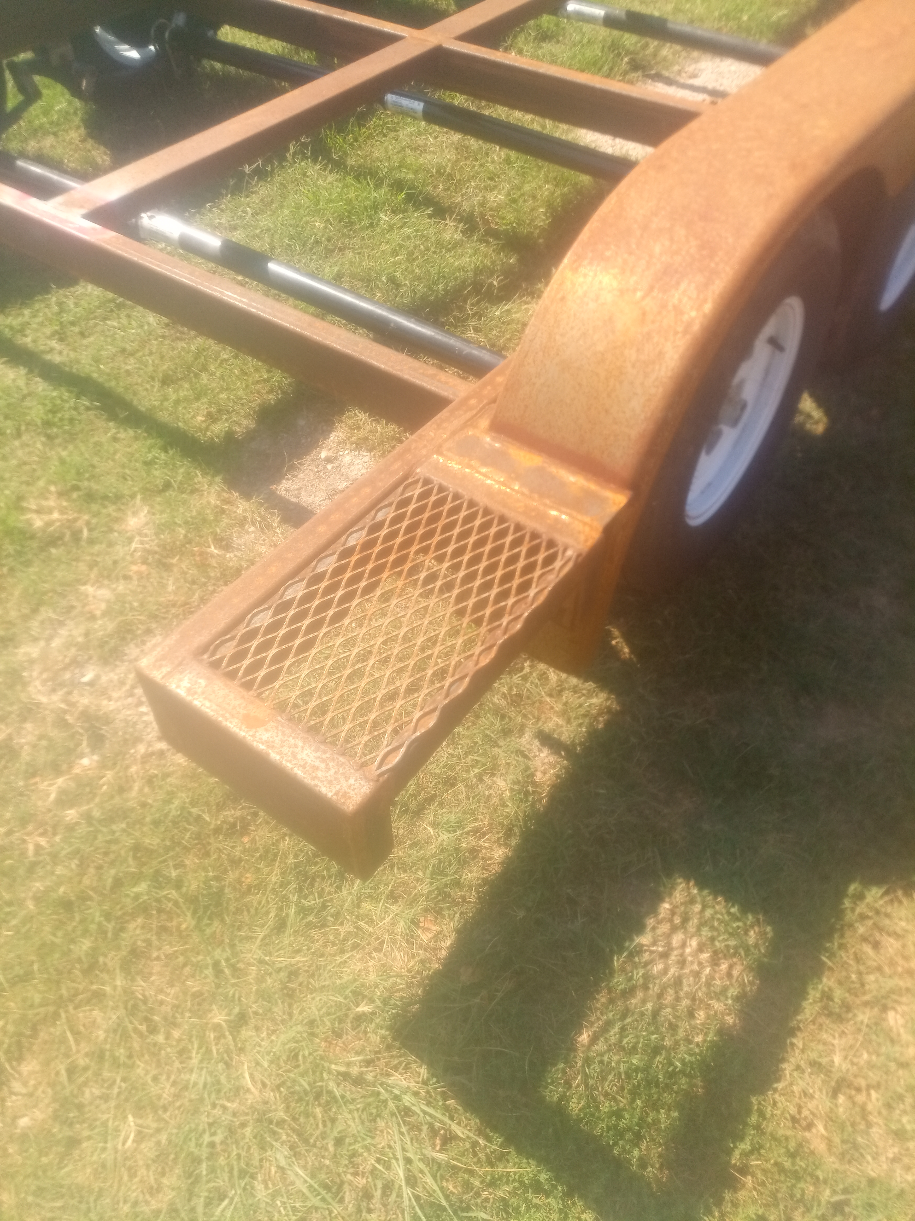
Since nobody likes to get the tow vehicle down in the water, I designed an 8' telescoping tongue. I am still waiting on parts to make it automated. The trailer is all sealed box-beam construction and expanded metal tread plates.
Front steps on trailer
Rear trailer steps
It has to be sand-blasted and powder coated yet. Then I can mount the bunk boards and electrical.

